Vega Build Guide
Pages
Vega Build Guide - Page 4
Assembling the internals
-
Prepare and tune the stabilizers needed for your preferred layout, if not done already.
Prepare and lube the switches as well. -
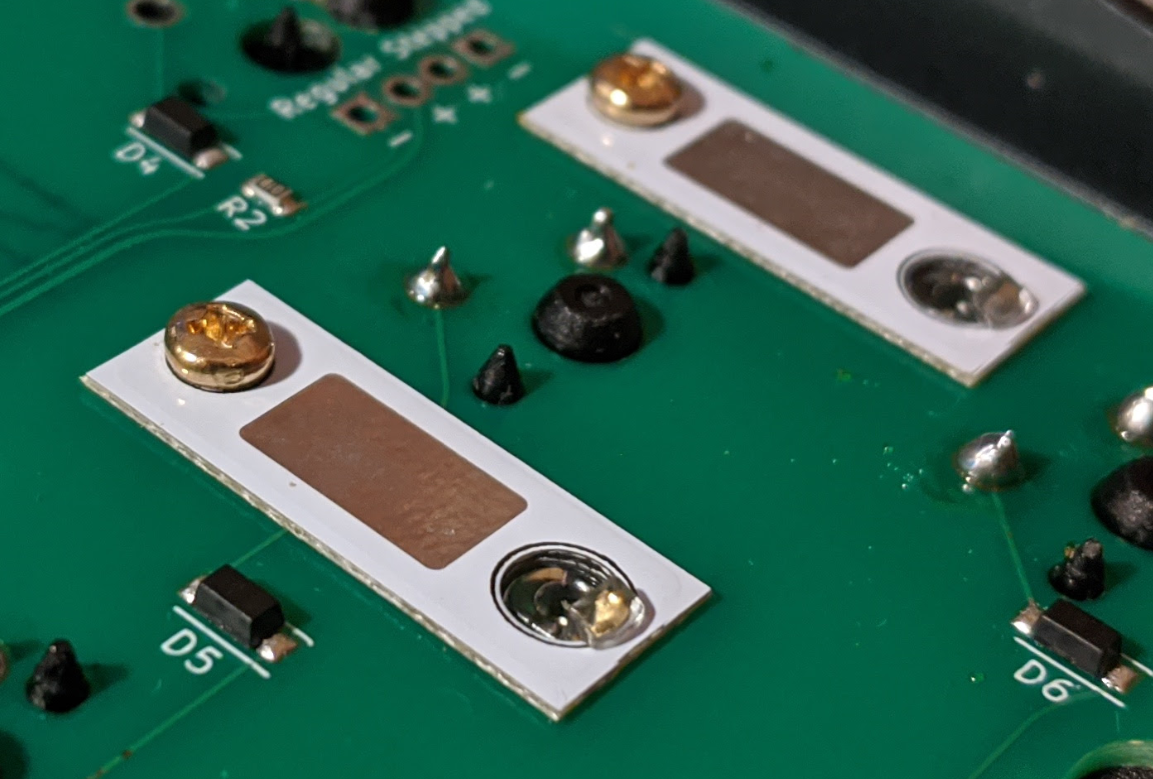
Mount the stabilizers onto the PCB using the provided shims to fill the gap on the thin PCB.
The side with the copper artwork (logo) should face away from the PCB.
An example of shim use is shown below; the shim goes on the bottomside of the PCB, with the hook of the stabilizer hooking both the shim and the PCB.
Note: The pictured shim is an earlier revision; however, its usage remains the same.
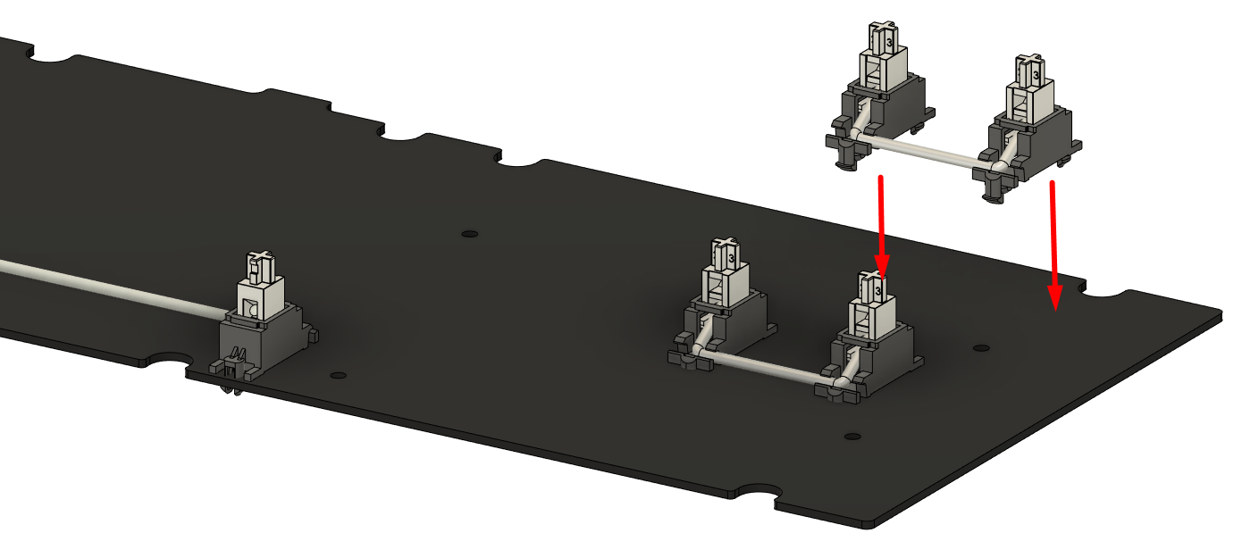
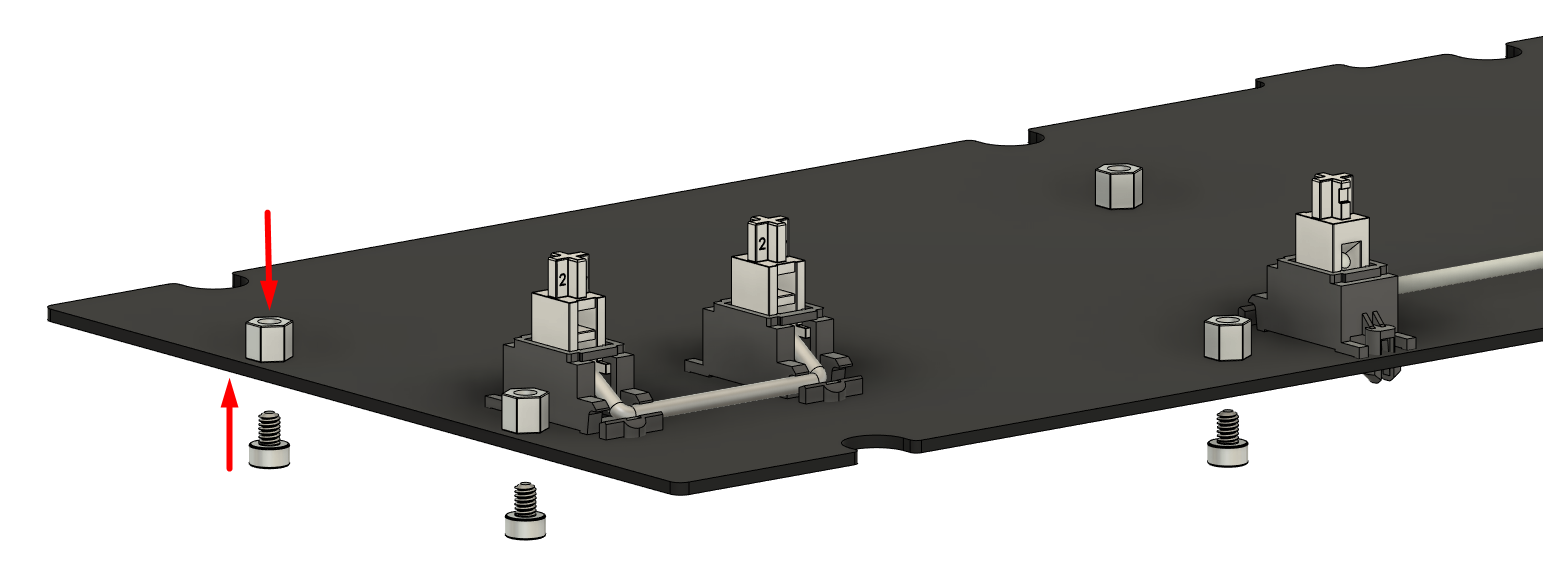
- Open the pack of hotswap standoffs and screws.
For hotswap users who plan to swap switches in the future without case disassembly: Install a standoff at each of the 9 standoff screw holes on the PCB, and secure using the short hotswap screws from the bottom.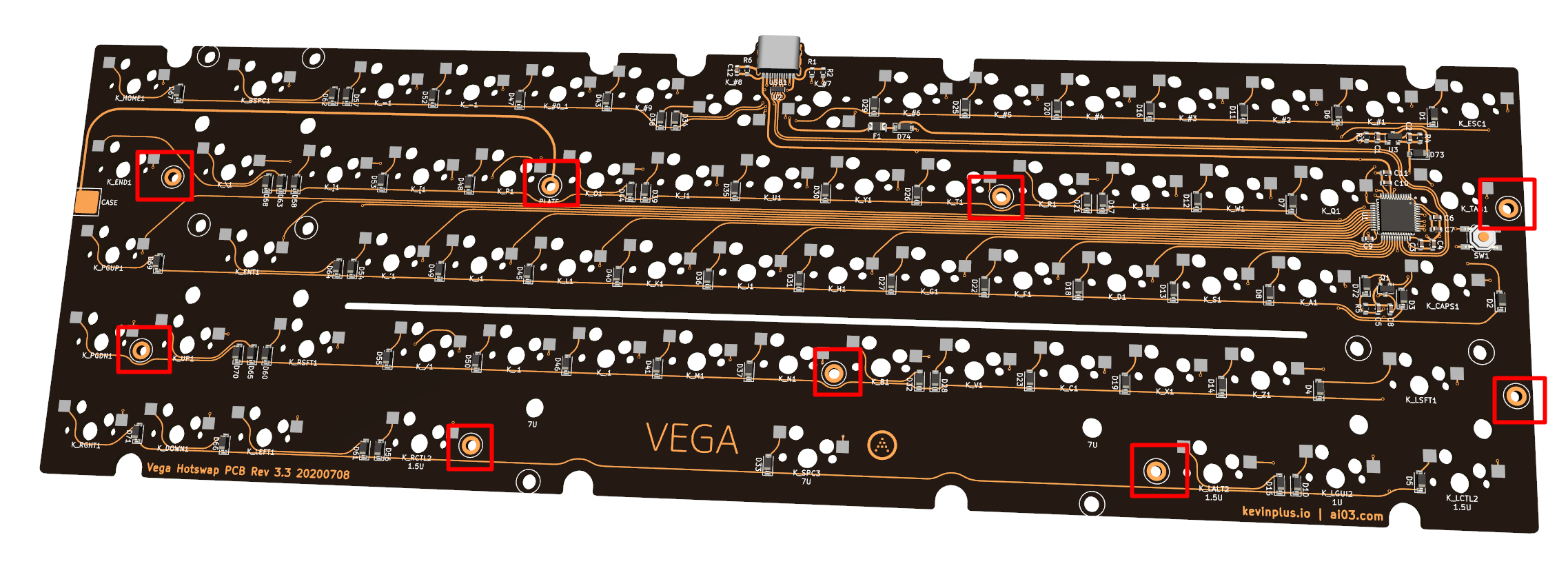
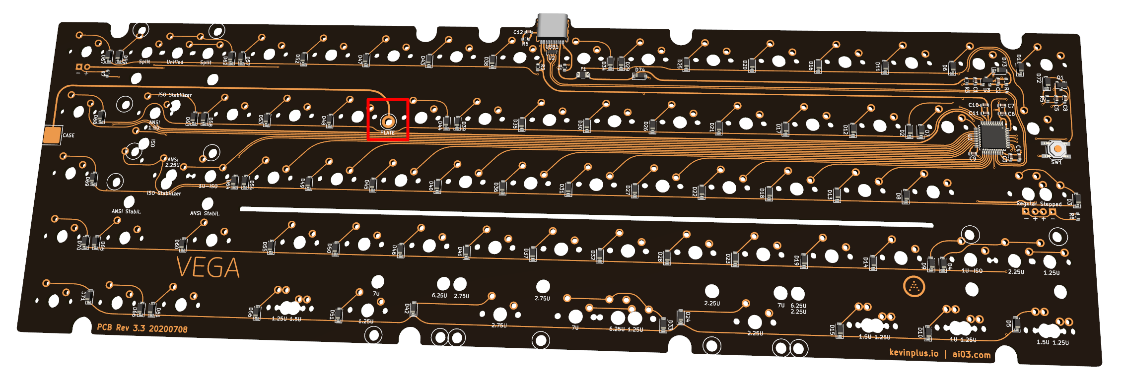
For users with an aluminum plate: Install one standoff at the standoff screw hole on the PCB marked “PLATE”, and secure using a short hotswap screw from the bottom. This is necessary to properly handle static discharges that occur against the plate.
For all other users: You may leave the standoffs unused for softest typing feel if wanted. However, please note the following:
- The PCB may begin to slide off after very extended use, at which point you may need to re-seat the PCB against the switches by pushing it back into place.
- Swapping switches will require case disassembly to firmly seat the switches against the PCB.
For securing these standoffs, install cylindrical head screws from the other side provided in the same hotswap hardware kit package.
-
If you plan to use the foam midlayer, install it above the PCB at this stage.
Our personal recommendation is to install it if you prefer a calmer/more muted sound; if you dislike it, it is always possible to rebuild it without on the hotswap variant.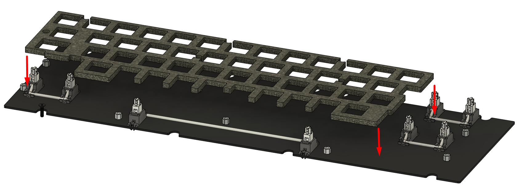
-
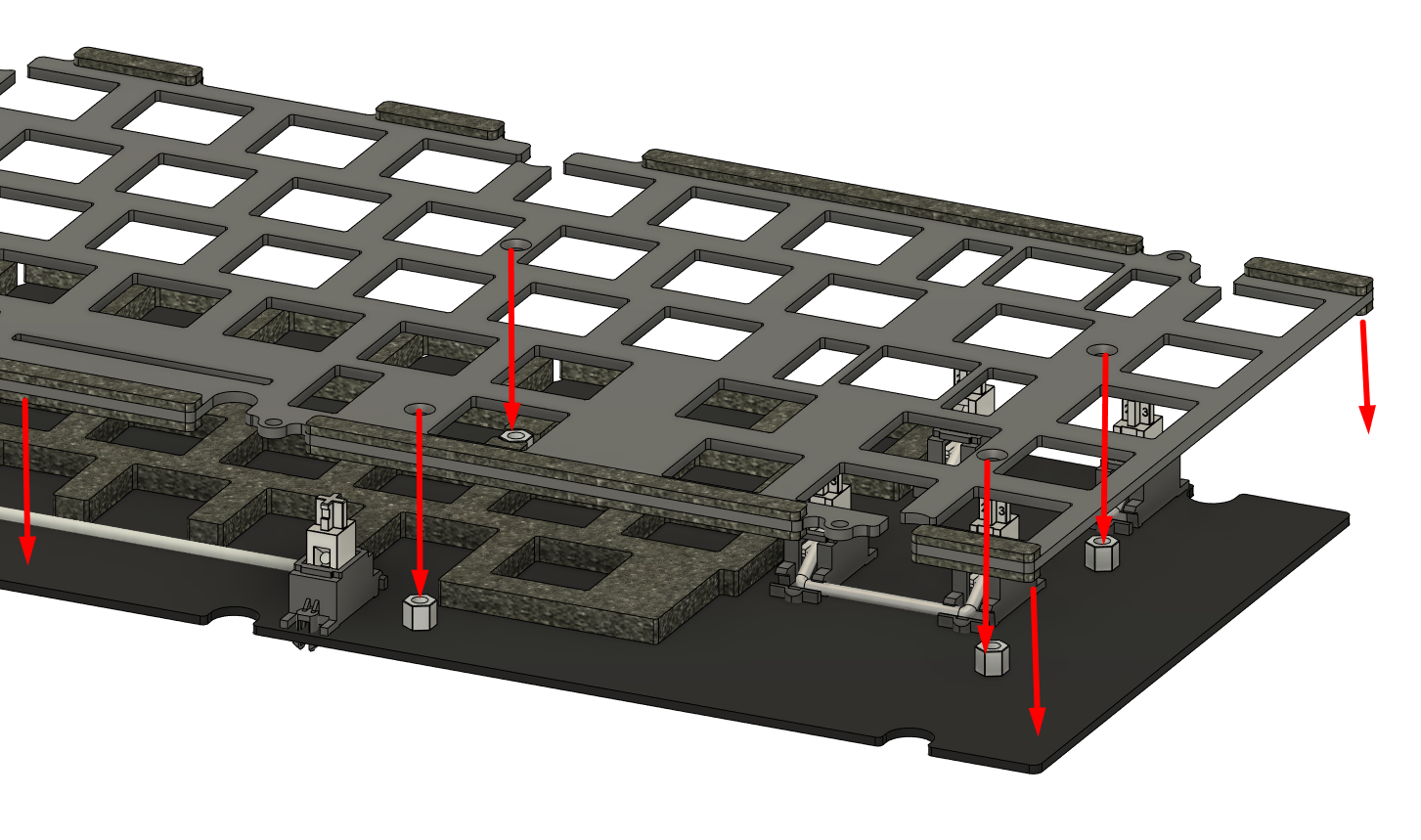
Install the plate so that the screw holes on the plate align with the standoffs and stabilizers installed onto the PCB.
-
Secure the plate to the standoffs using the countersunk hotswap screws for any standoffs used.
-
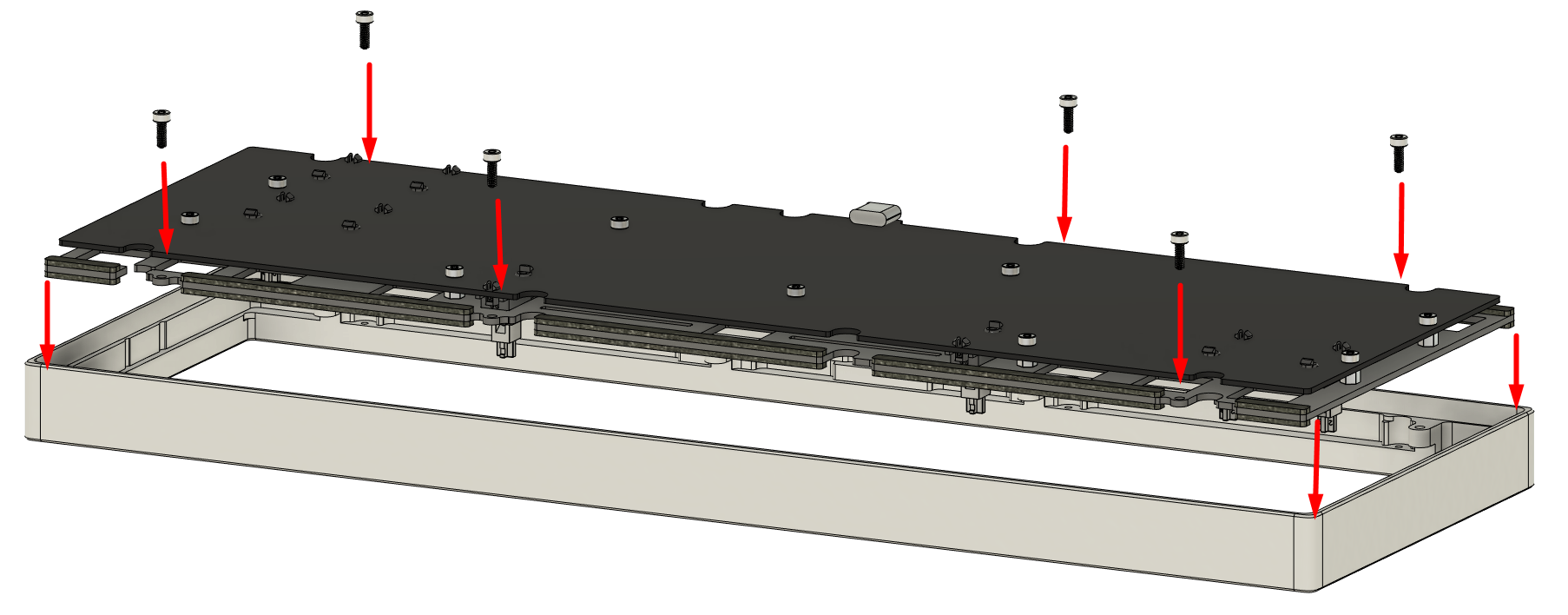
Place the assembled plate-PCB structure into the top case half, making sure that the plate goes within the vertical rectangular gaskets placed onto the top case half.
Secure this structure to the top using the temporary plate screws.
- Prepare to install switches.
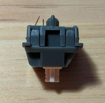
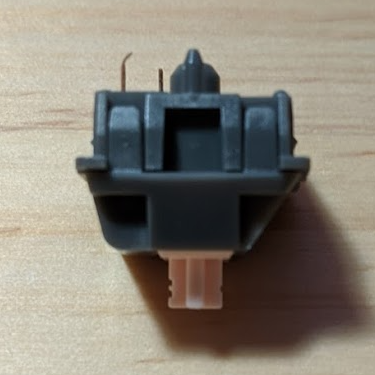
First, take the switch and flip it upside down.
Check for any sort of bent legs, and repair them by bending them back to be straight.
The following are examples of switches with bent legs.
Notice how the one on the right has a bent tip despite the rest of the leg being straight.
Either has the ability to destroy a hotswap socket; make sure to catch them before they enter the socket.
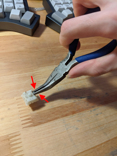
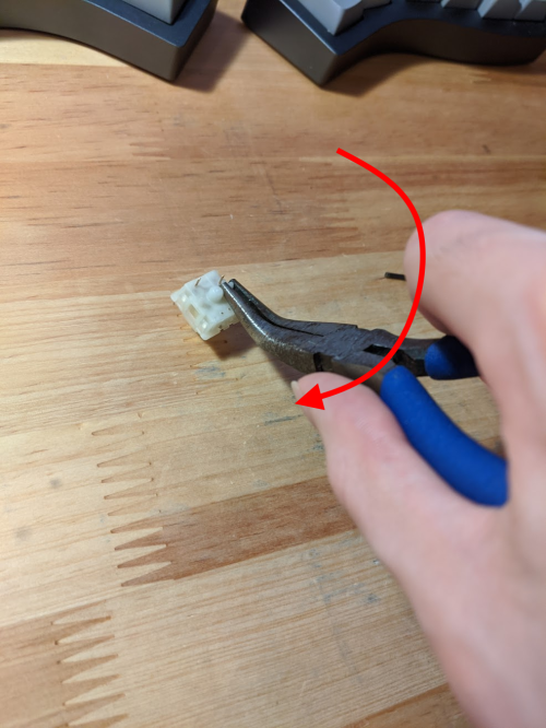
- Some switches are known to have very thick PCB-mount legs which exceed MX spec heavily, such as Gaterons.
For these switches, it is highly recommended to thin the legs by compressing them with flat head pliers prior to installation.
This can be done by closing the pliers against a leg and twisting it around to crunch the leg down.
Note: Do not apply forces so extreme that the switch shatters.
- After un-bending the legs with fingers, tweezers, flat pliers, or your tool of choice, carefully insert them to the plate-PCB structure.
Hold the PCB surrounding the switch and push the switch firmly down, making sure that the switch snaps into the plate and is firmly seated against the PCB.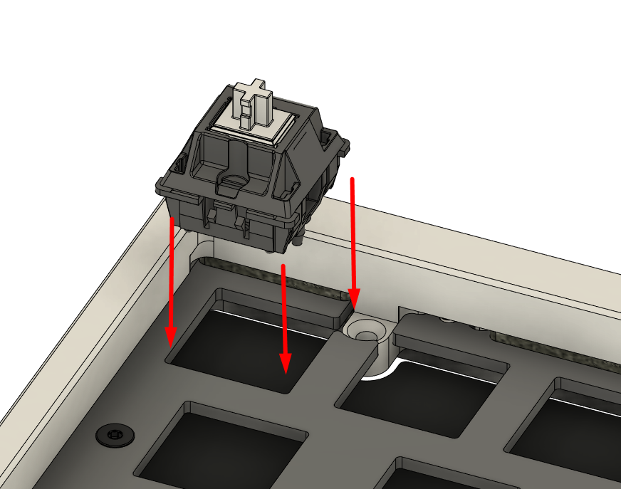
Make sure the orientation is correct: On the hotswap PCB, the keys 7 and 8 next to the USB connector are flipped to avoid obstructing the USB port.
-
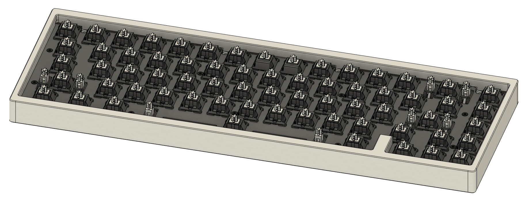
Repeat steps 7~9 for all switches. If assembling a soldering kit, solder the switches. Make sure that the switch is seated firmly against the PCB once soldered.
-
At this stage, it is highly recommended to connect the build to a computer and to verify that all keys send a keystroke. Note: The caps lock position is bound to Fn by default, and will not send a keystroke on its own. Instead, hold the caps lock position and press the numrow, and see if it sends F1~F12 rather than numerics.
-
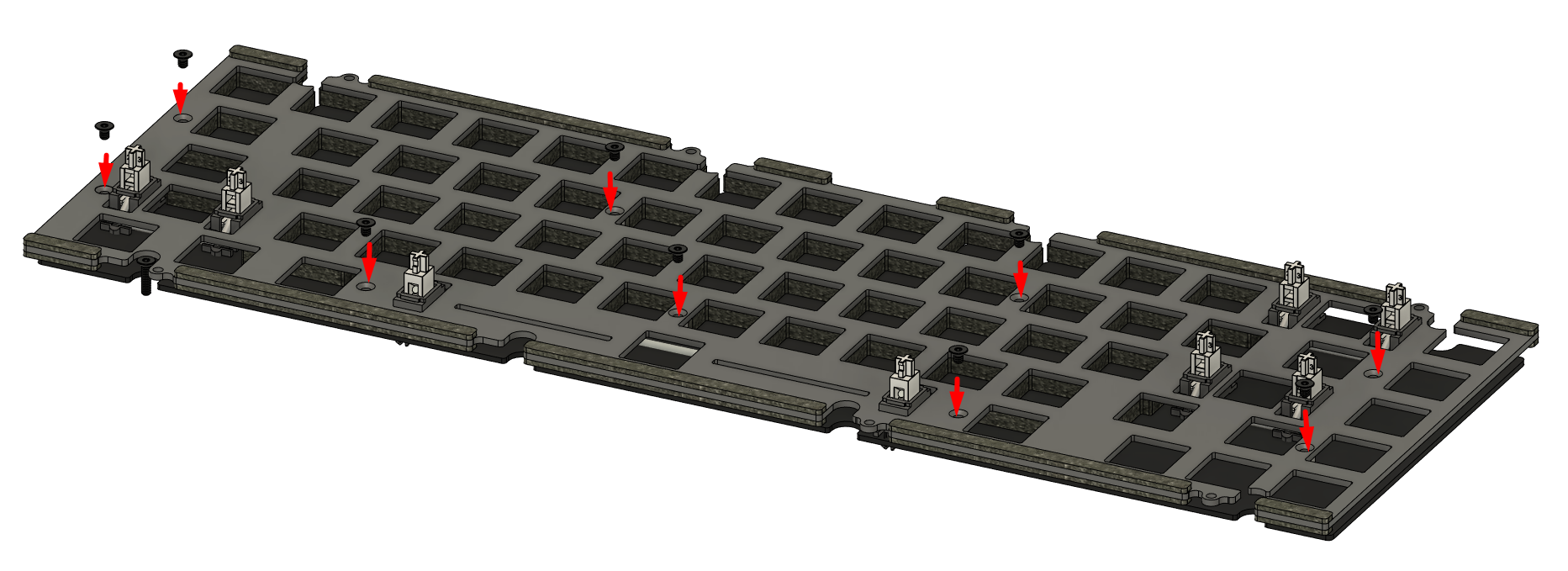
Flip the structure over, and remove the temporary plate retention screws.
Leave the assembly upside-down at this stage.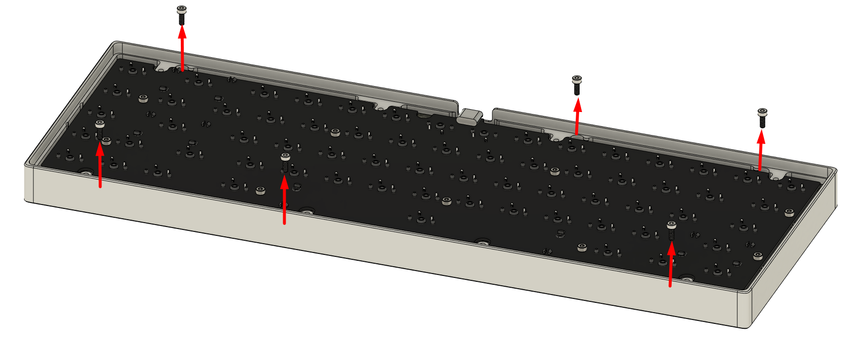
-
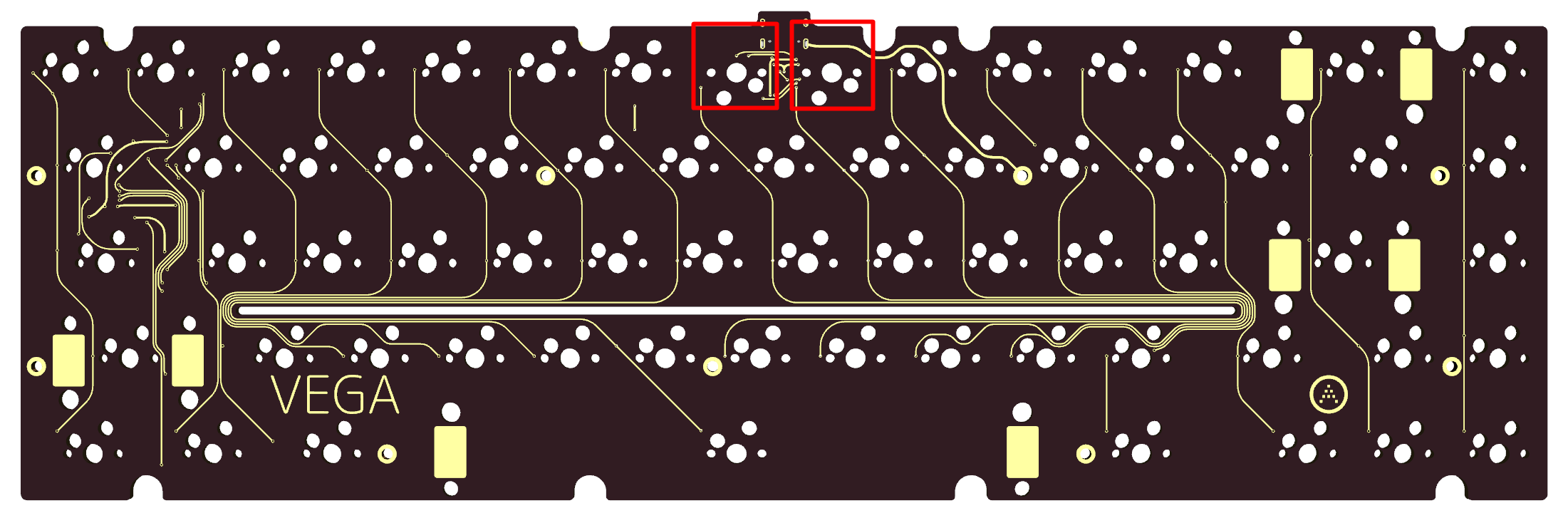
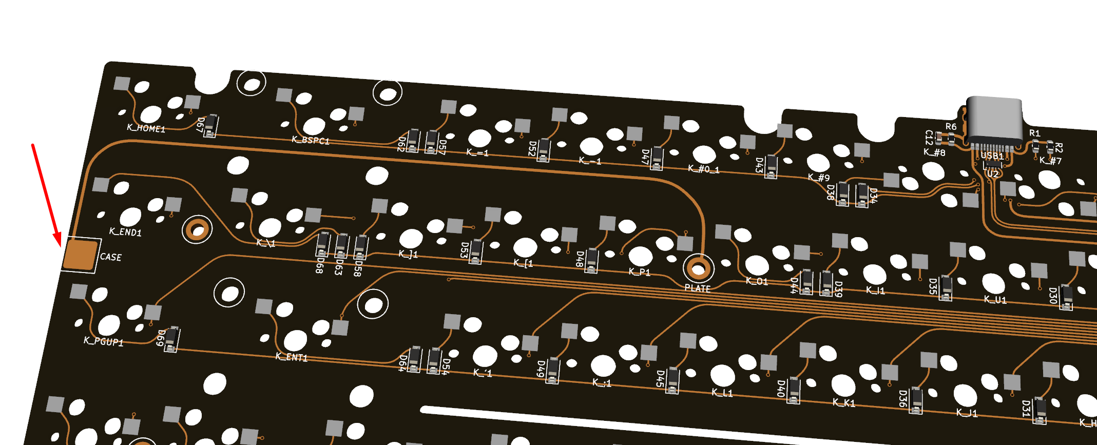
Install one of the provided grey conductive foam pads atop the exposed copper pad marked “CASE” on the PCB.
That was a lengthy section, but most of the hassle is out of the way at this point. Now to complete the assembly.
Next Page