Lunar II Build Guide
Pages
Lunar II Build Guide - Page 3
Assembling the board
Let’s begin with the case.
-
Remove the components from the box if not already done.
-
Use the supplied hex key to remove the plate screws.
-
Remove the plate from the case.
-
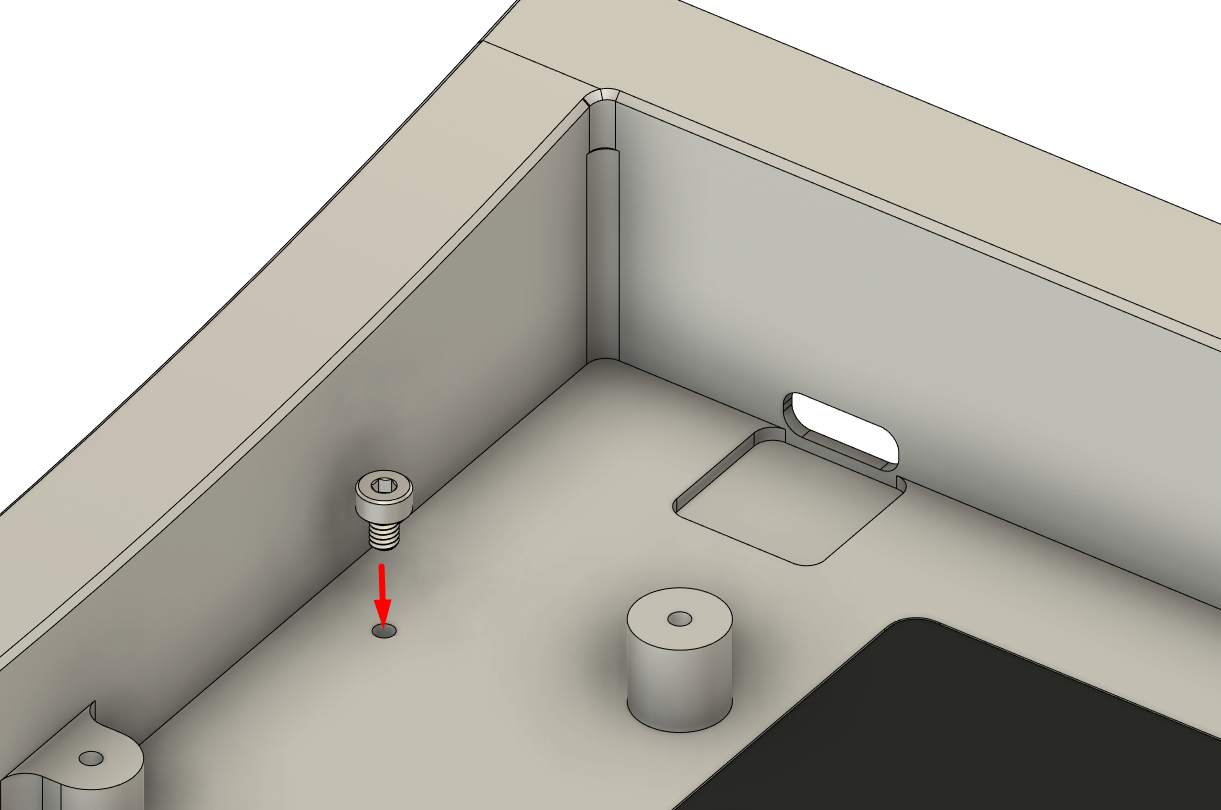
If no screw was inserted into the PCB-conducting screw position out of the box, install this screw.
-
Flip the case over.
Install the provided rubber feet into the insets.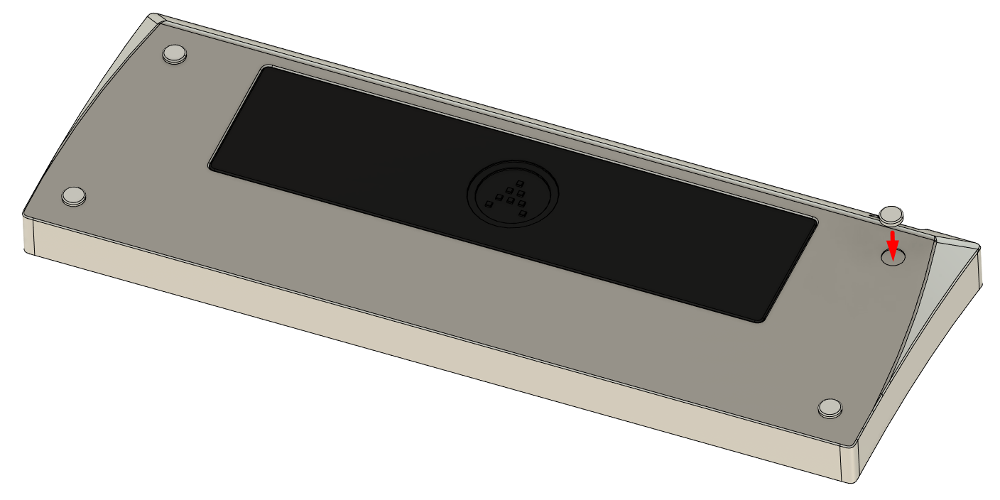
-
Install the stabilizers and spacebar pipe onto the plate.
Make sure the spacebar pipe matches the spacebar orientation you are using.
Make sure the stabilizer inserts are oriented the correct way; the wire clip side should be facing away from the switch cutout.
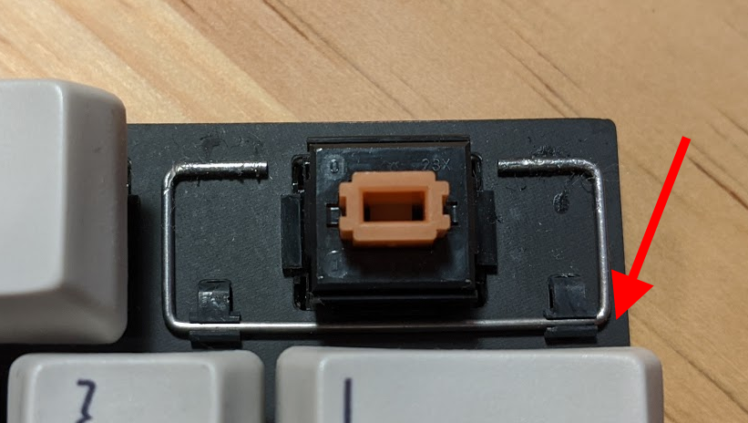
Note: The stabilizers and spacebar pipe will not be rendered in the images below due to not having a 3D model on hand.
-
Tune and test the switches if not already done.
Snap the switches into the plate.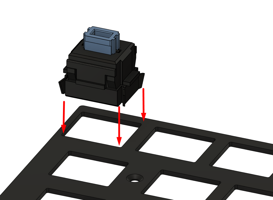
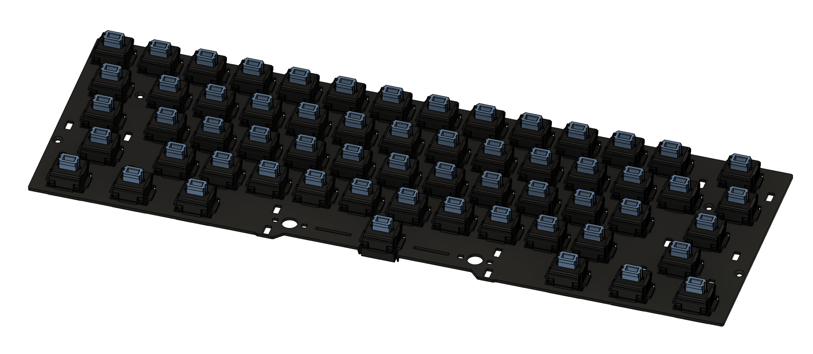
-
Insert the PCB against the switches.

-
Solder the switches into place, making sure that the PCB is seated firmly against the switches.
Excessive gaps between the plate and PCB may negatively affect acoustics. -
At this stage, it is highly recommended to connect the PCB to a computer to test the functionality of all keys.
Repair any faulty joints and replace any non-functional switches. -
If installing the solenoids:
- Align the two solenoids to the solenoid bracket.
Pay attention to the following:
- Place the solenoids so the cables exit on the top-side.
- The solenoids should fire inwards towards each other, with the springs on the outer side keeping the plunger away from each other unless manually pushed inwards by hand.
- The solenoid bracket should be positioned so the U-shaped cutout is at the top, and so that the screw holes line up with the solenoids.
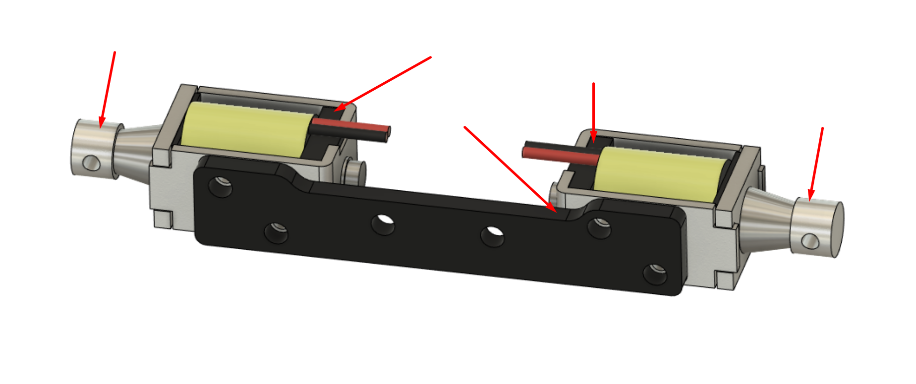
-
Install the M2x3mm screws to secure the solenoids to the bracket.
It is recommended to tighten the screws with the assembly on a flat surface to prevent the solenoids from being secured down at an angle.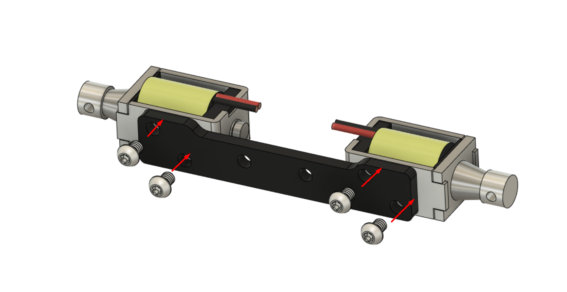
-
Remove the weight screws, then remove the weight from the case.
Be careful during this process to avoid scratching or denting the parts - the weight installs perpendicularly to the inner case bottom surface rather than the exterior one.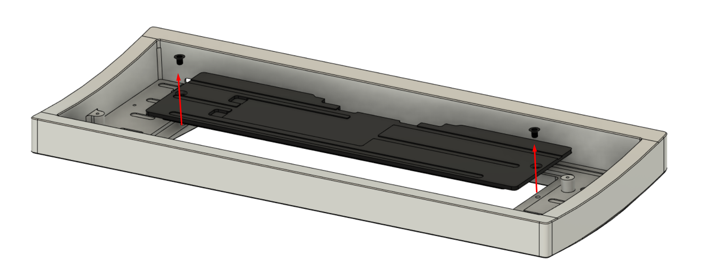
-
Install the solenoid assembly to the rear of the weight, and secure it using the M2x4mm screws.
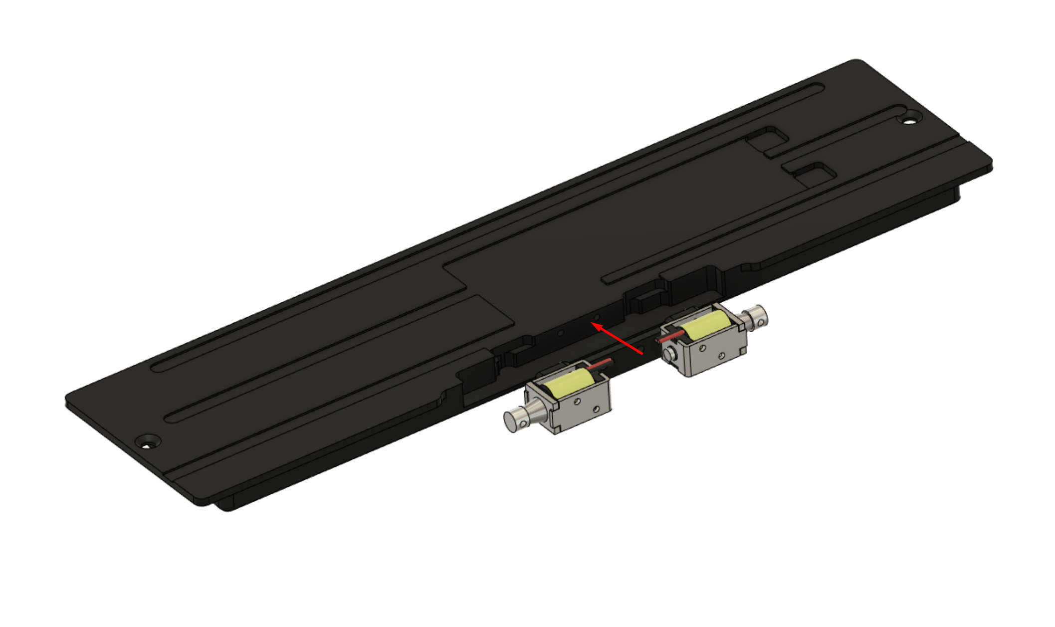
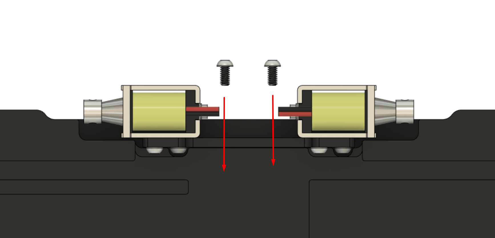
-
Reinstall the weight into the case with the two weight screws.
Take care to avoid damage to the weight and case, and make sure the solenoid cables do not get caught between the case parts in the process.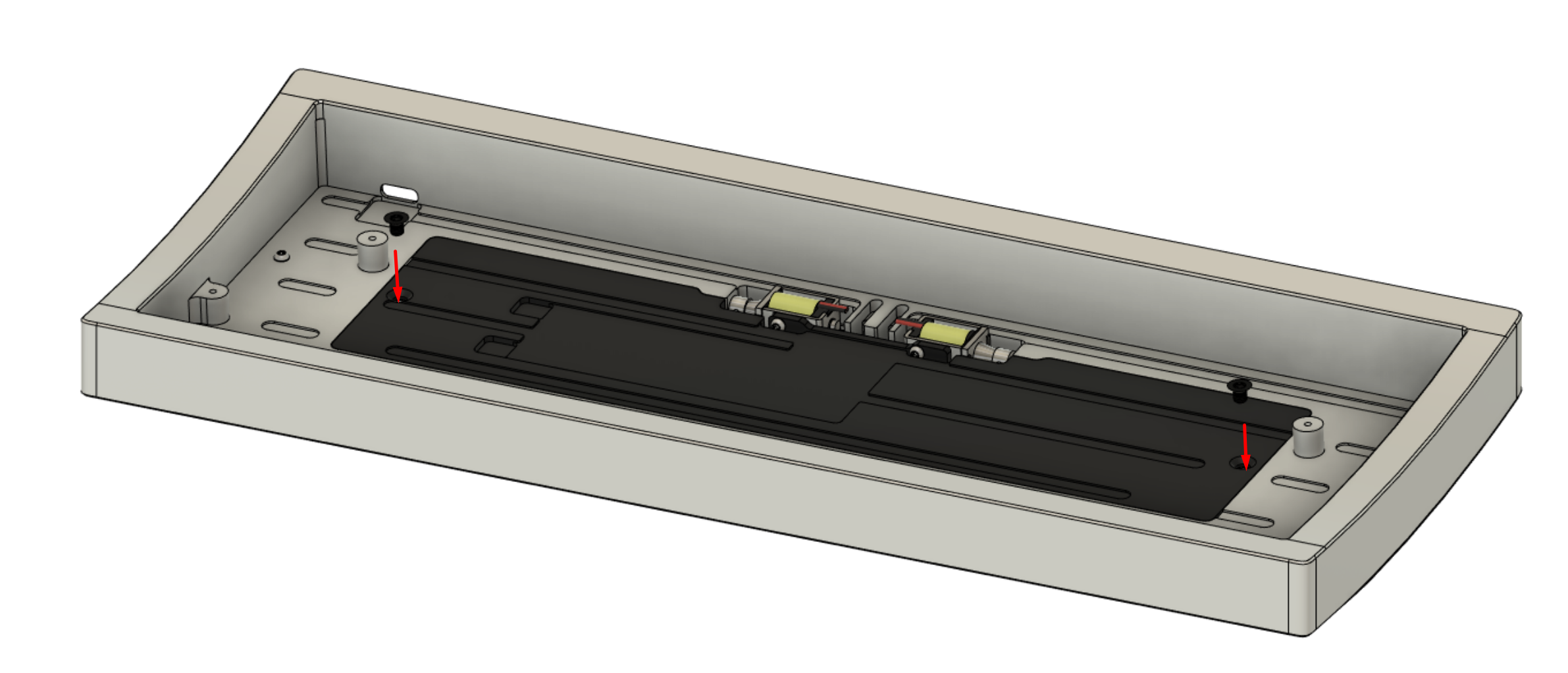
The initial solenoid installation is now complete.
- Align the two solenoids to the solenoid bracket.
-
Place the provided ring gaskets atop the four plate mount points.
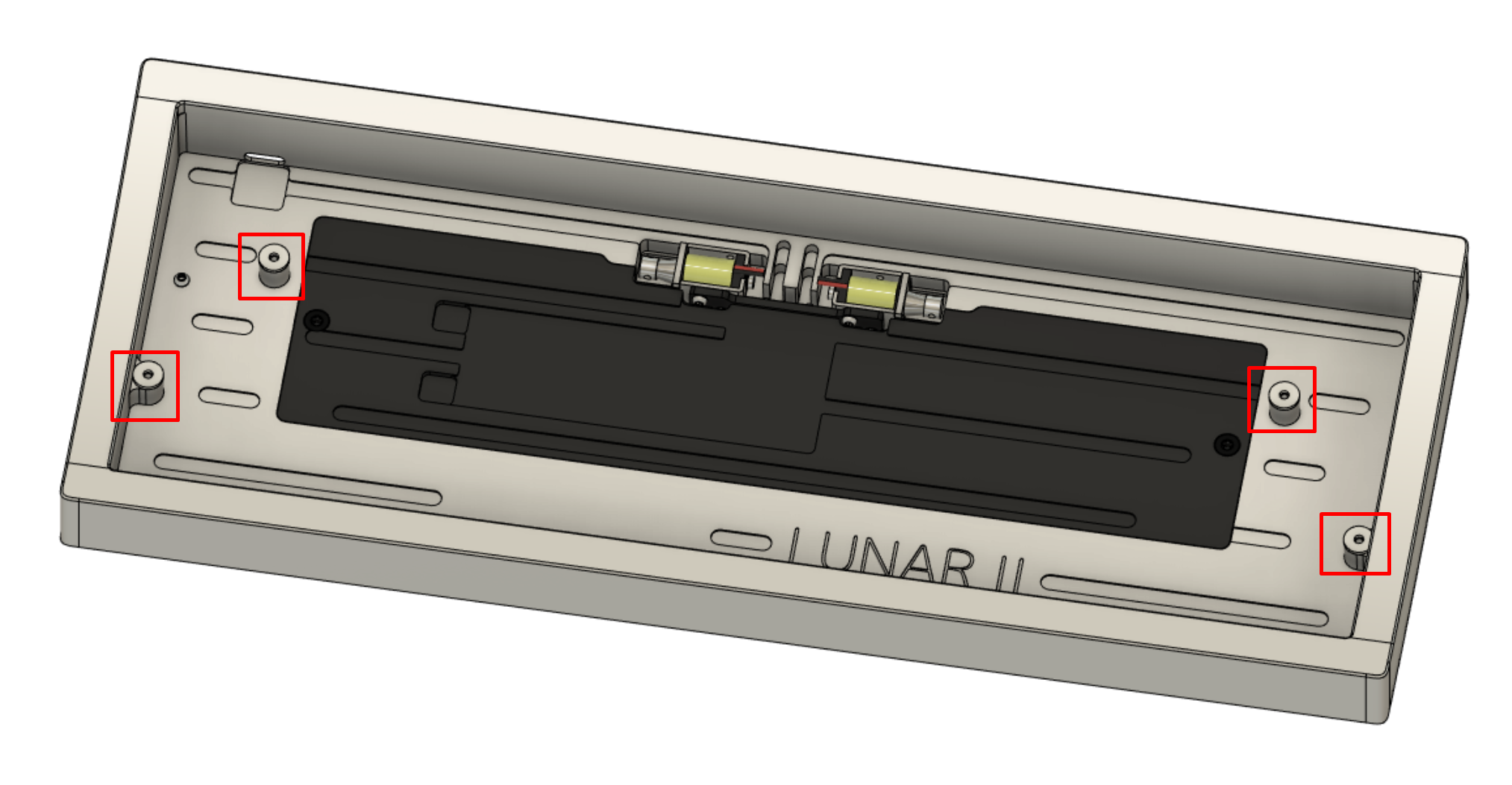
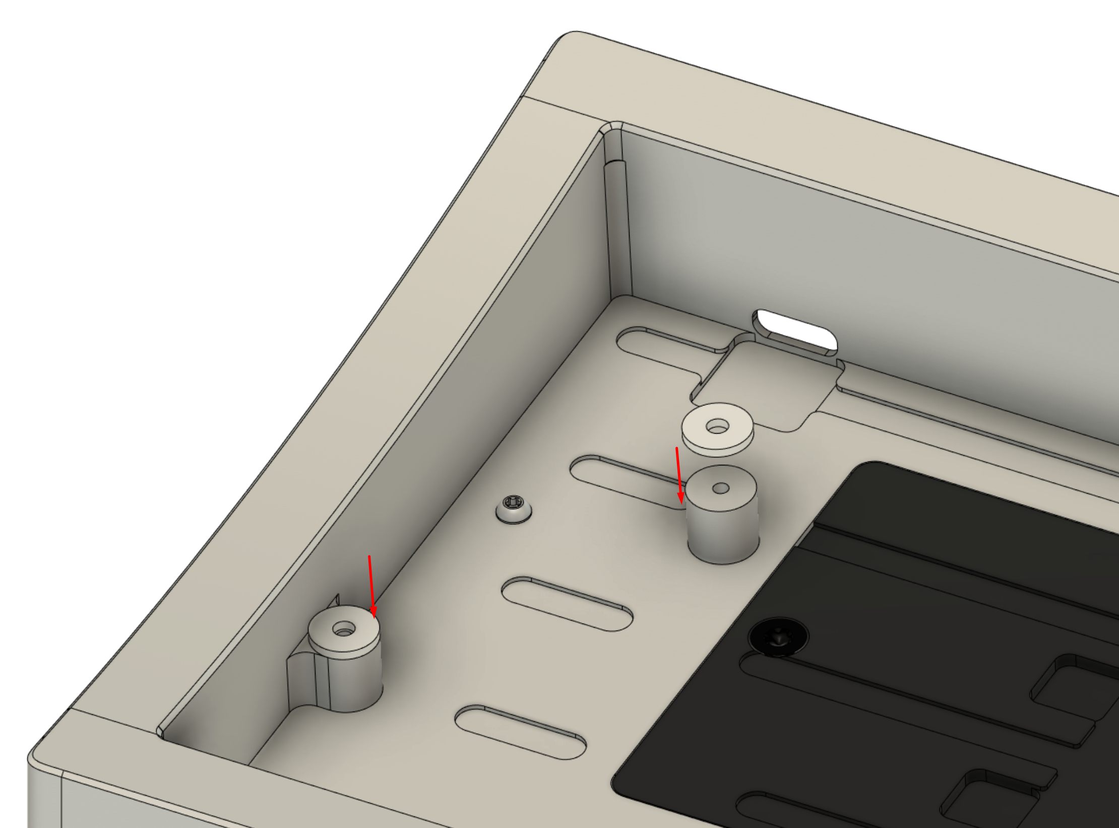
-
If installing the solenoids:
Connect the solenoids to the PCB.
There is no specific ordering as to which solenoid goes to which connector, but make sure that you insert the connector in the correct orientation - forcing it in upside-down may damage the PCB.
Once assembled, the cables should follow this general path along the case-side cutouts.
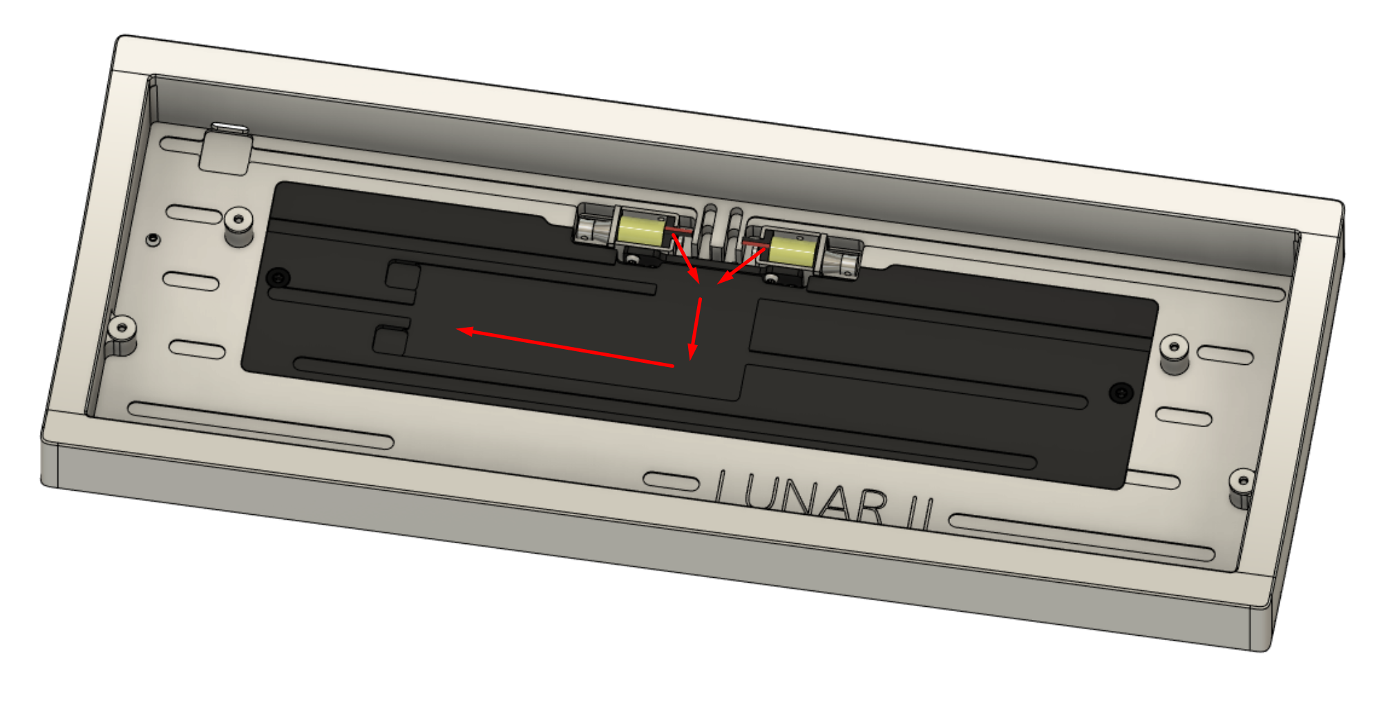
-
Install the provided silver square conductive foam pads onto the exposed copper area on the PCB marked “CHASSIS”.
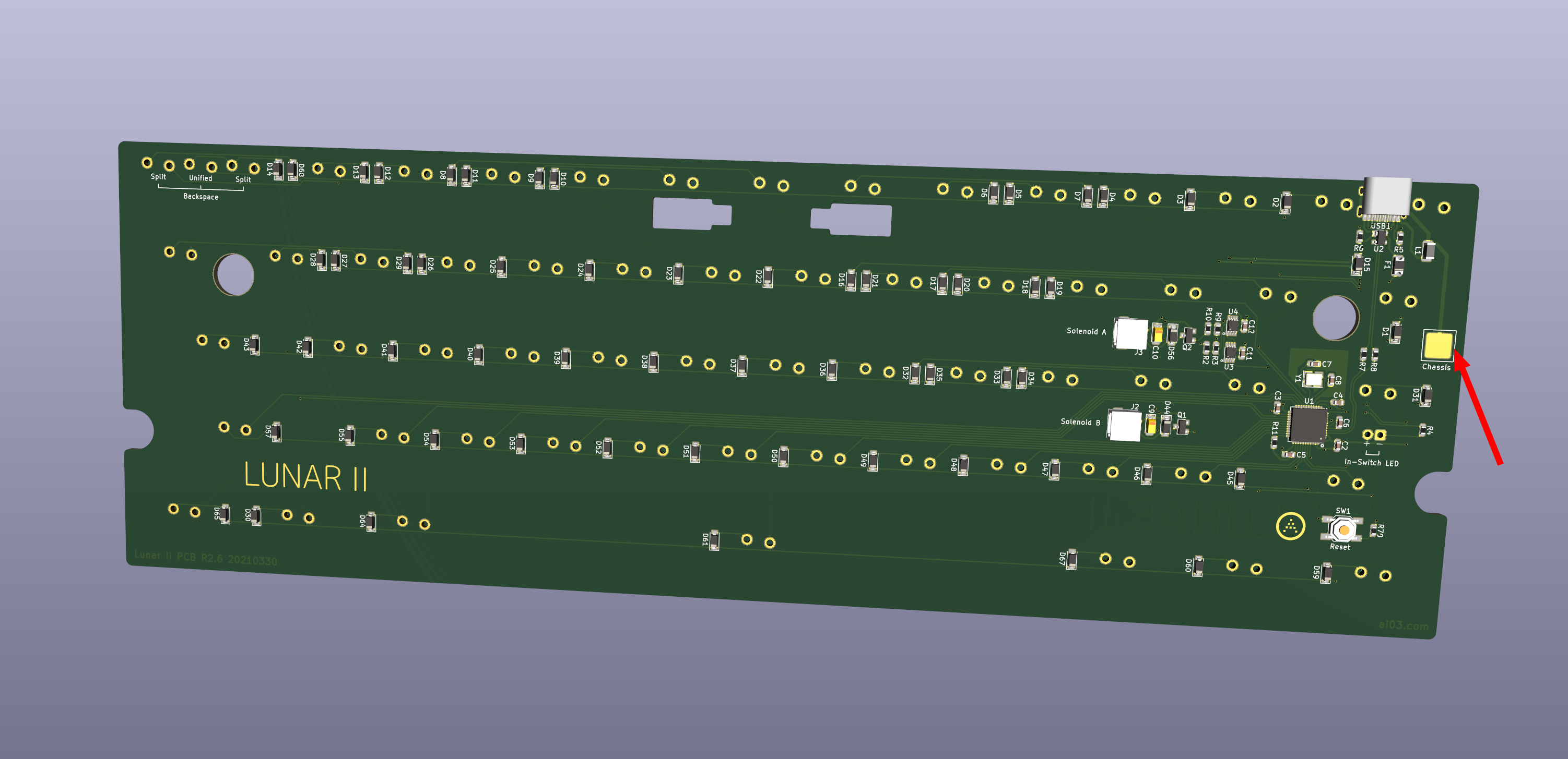
-
Insert the switch-plate-PCB-stabilizer assembly into the case.
The plate mount points should pass through the cutouts on the PCB.
If you are using the solenoids, take care to route the cables - make sure they do not get caught between the case and the internals.
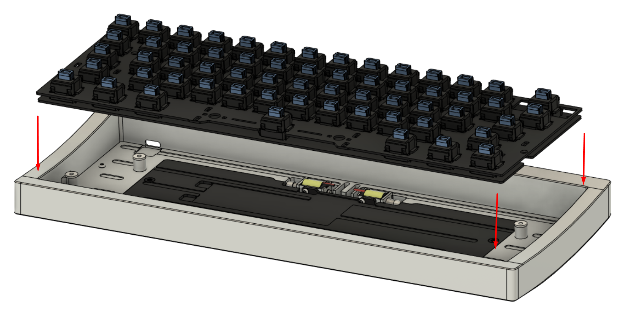
-
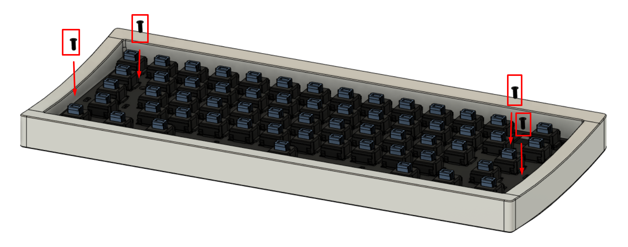
Install the four plate screws, compressing the plate gaskets lightly and equally.
Do not overtighten - the internals might sit too low and bottom-out against the case.
-
Install the keycaps.
Test some keystrokes and verify that they are sent.
Congratulations! You have fully assembled the Lunar II.
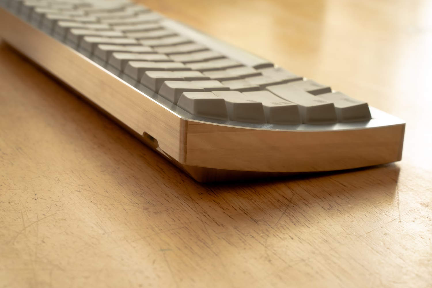
Now you are ready for the keymap editing and final remarks.
Next Page