Altair(-X) Build Guide
Pages
Altair(-X) Build Guide - Page 5
Putting it all together
The only thing left is to connect the ribbon cable and to fit it all together.
However, this can be a bit tricky - please proceed with caution:
- Always move parts around gently and carefully.
- If you ever feel a “tug”, stop immediately - the last thing you want to do is shear the cable apart or rip the connectors off the PCBs.
-
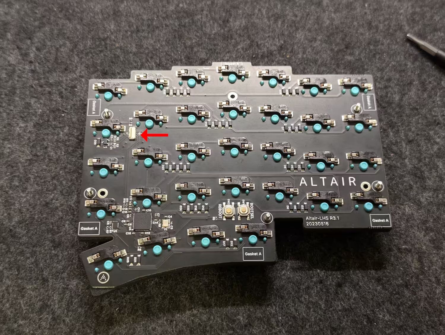
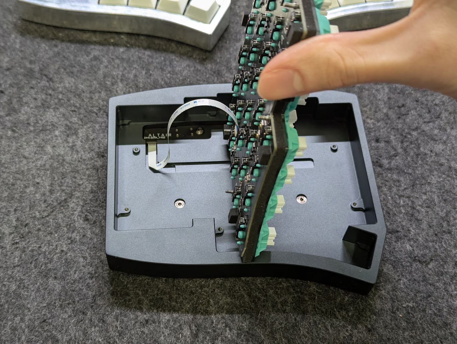
Prepare the internals by opening the FFC connector on the main PCB - lift the latch to its “upright” position if not already in that position.
The position of the connector on the PCB is shown below.
-
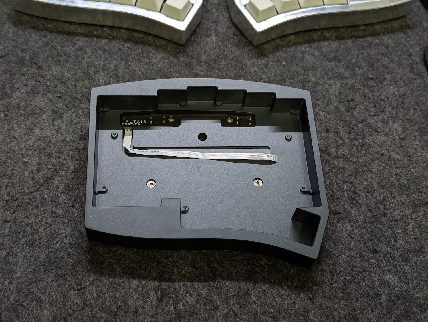
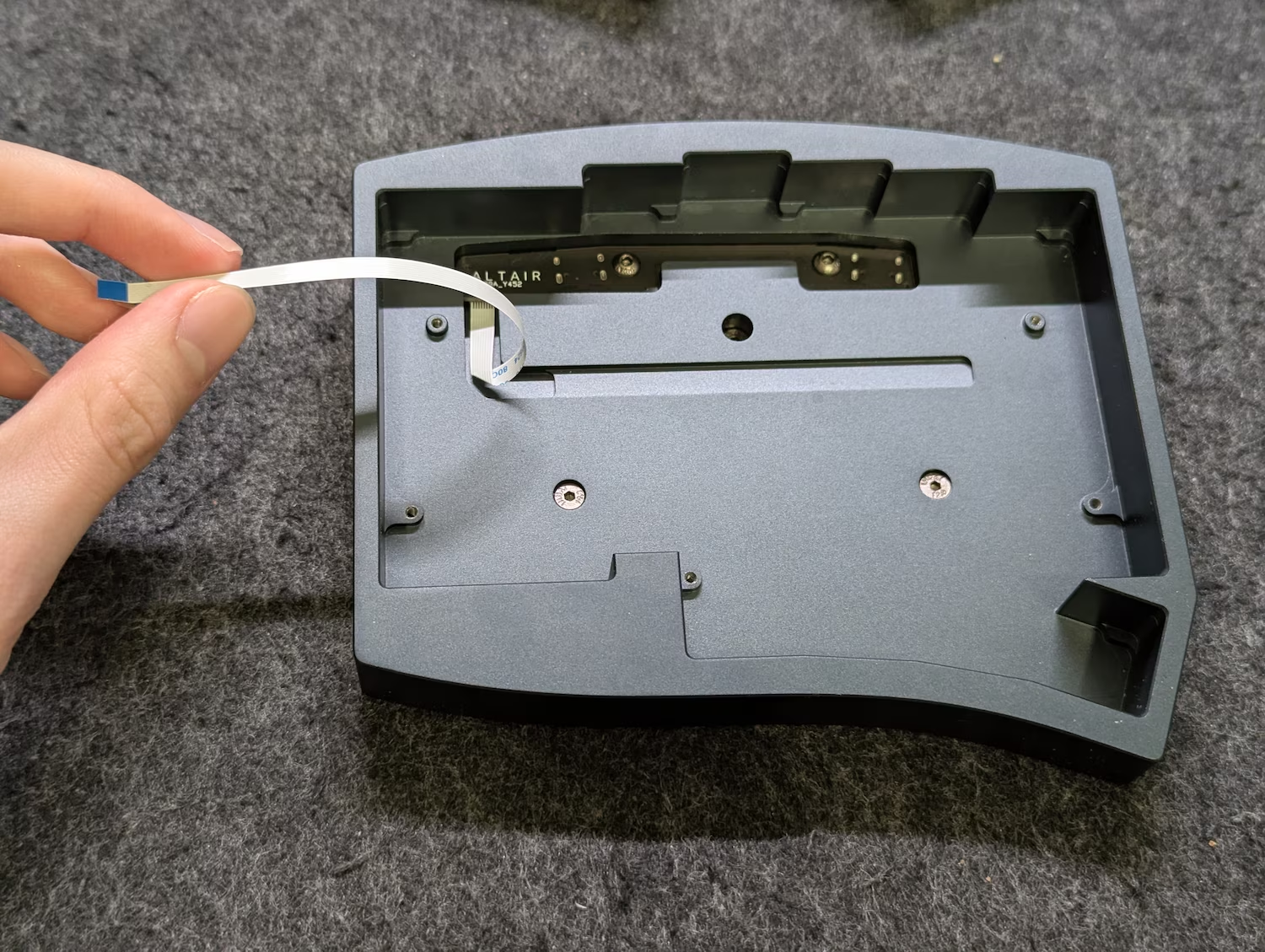
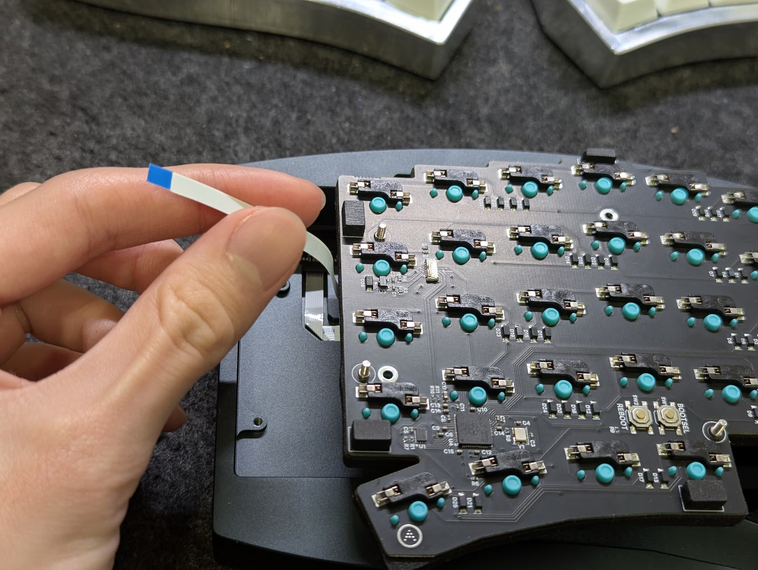
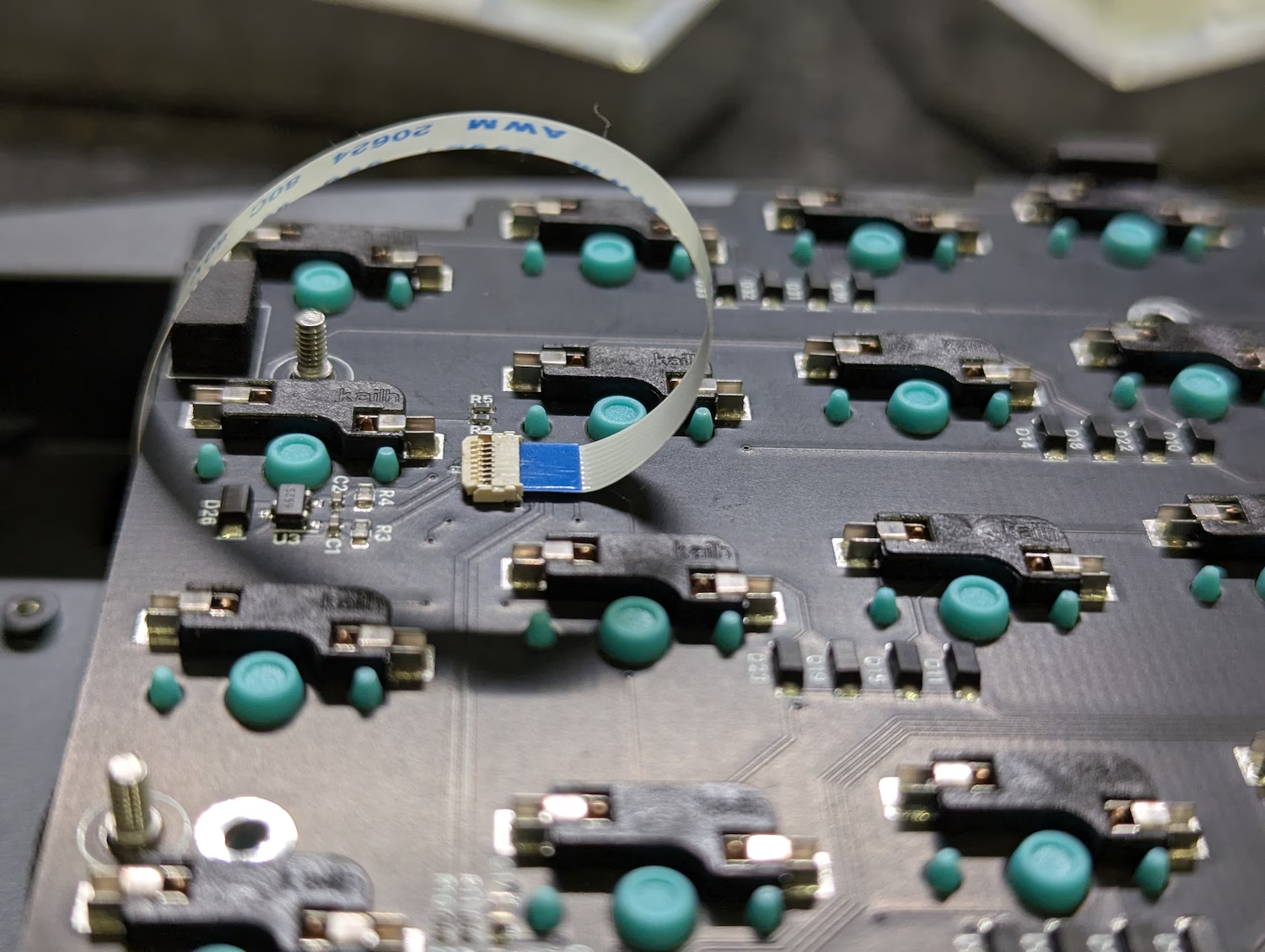
Prepare the case assembly, and lift the FFC cable end out of the case as shown below.
The cable should be simply bent outwards without any twists, with the blue tape on the end facing upwards.
-
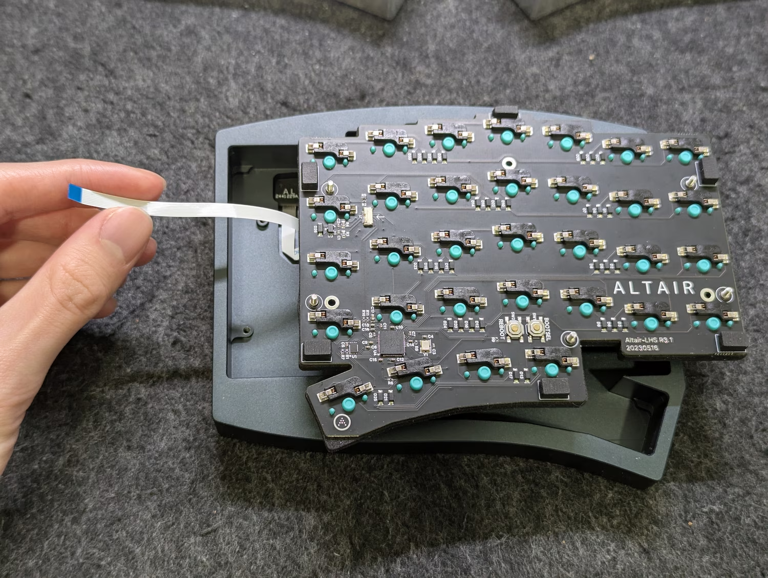
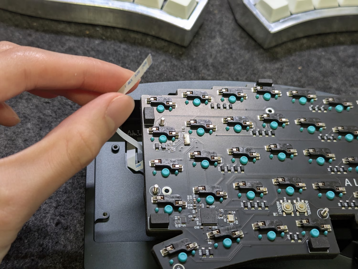
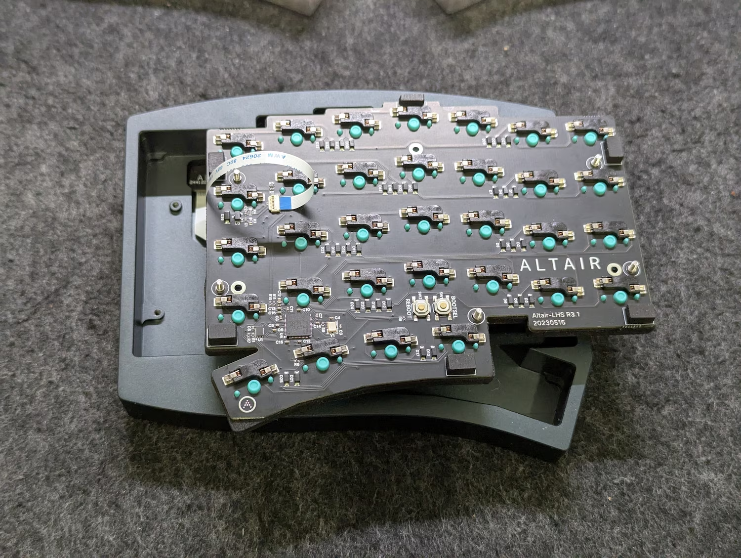
Place the PCB-plate-switches assembly upside-down as shown below, with the edge of the internals roughly aligned to where the FFC exits the daughterboard.
-
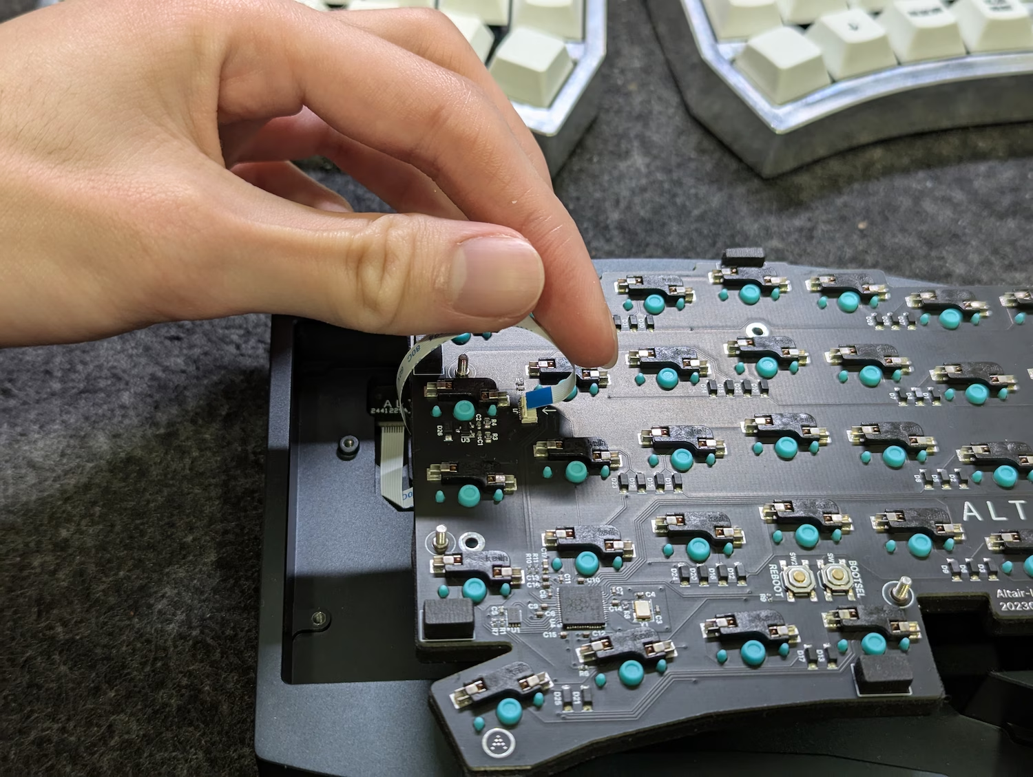
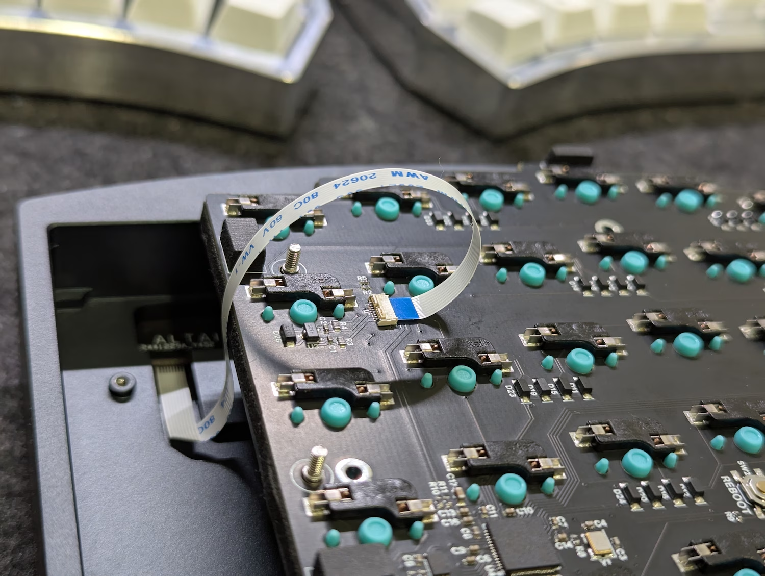
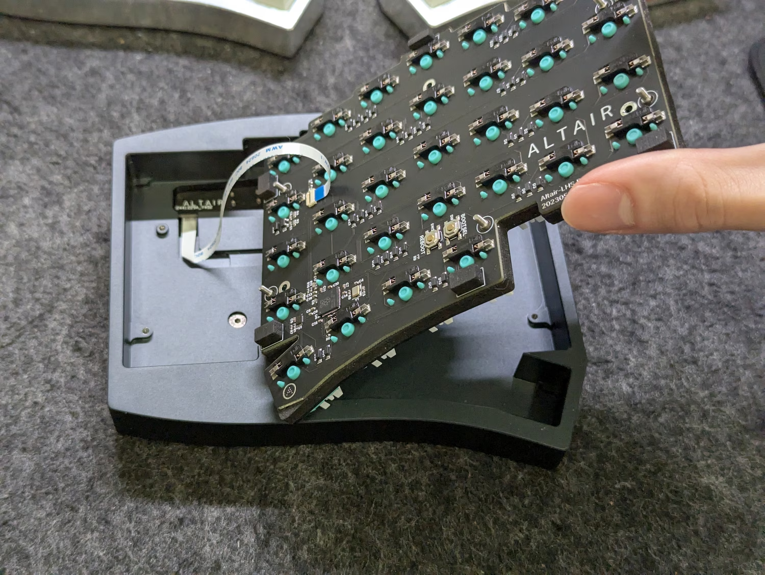
Bend the FFC in a loop as shown below, and insert it into the FFC connector on the main PCB.
Make sure that the cable does not have any twists once complete.
-
Insert the cable all the way, and verify that it is inserted straight as was done with the daughterboard.
Latch the FFC connector into its “down” position to secure the cable into place.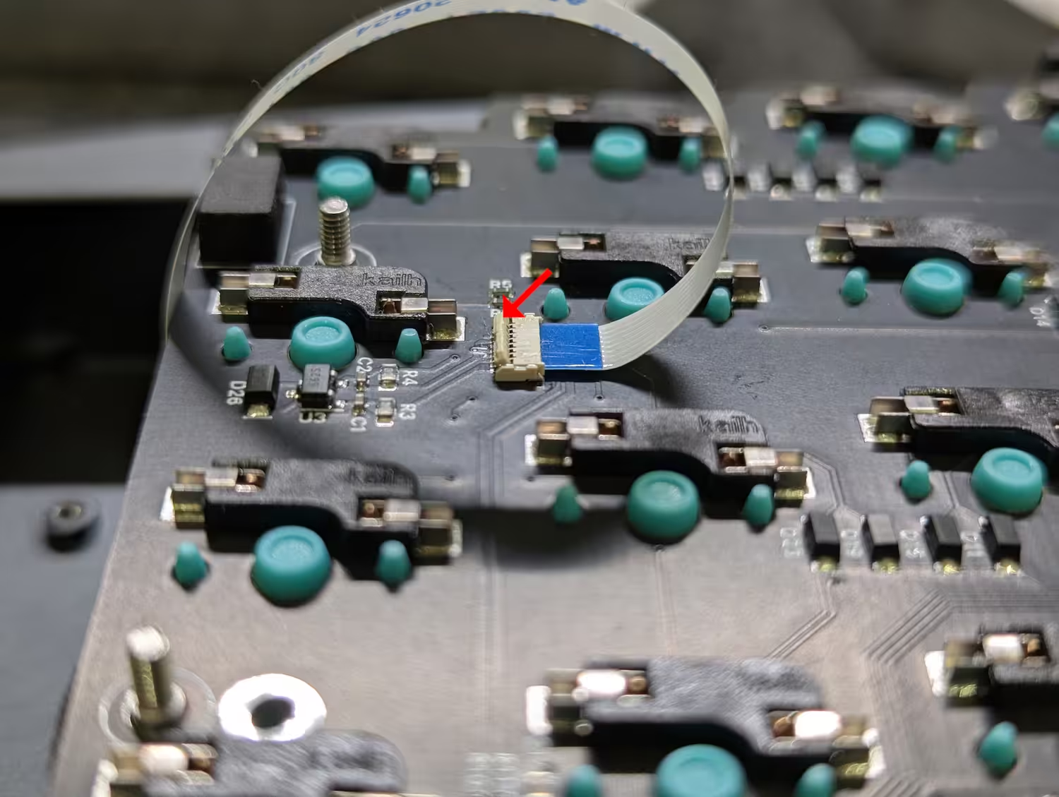
-
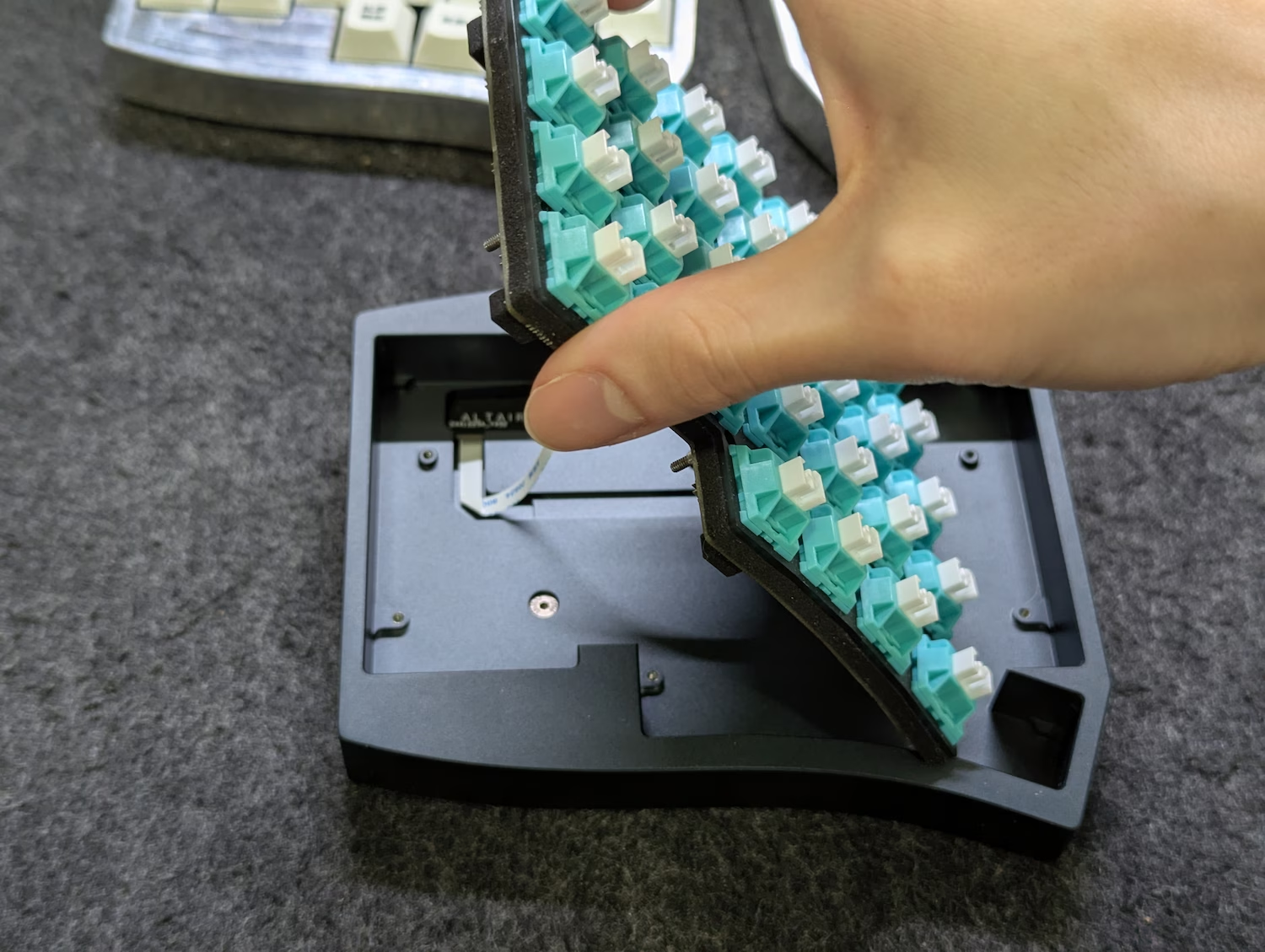
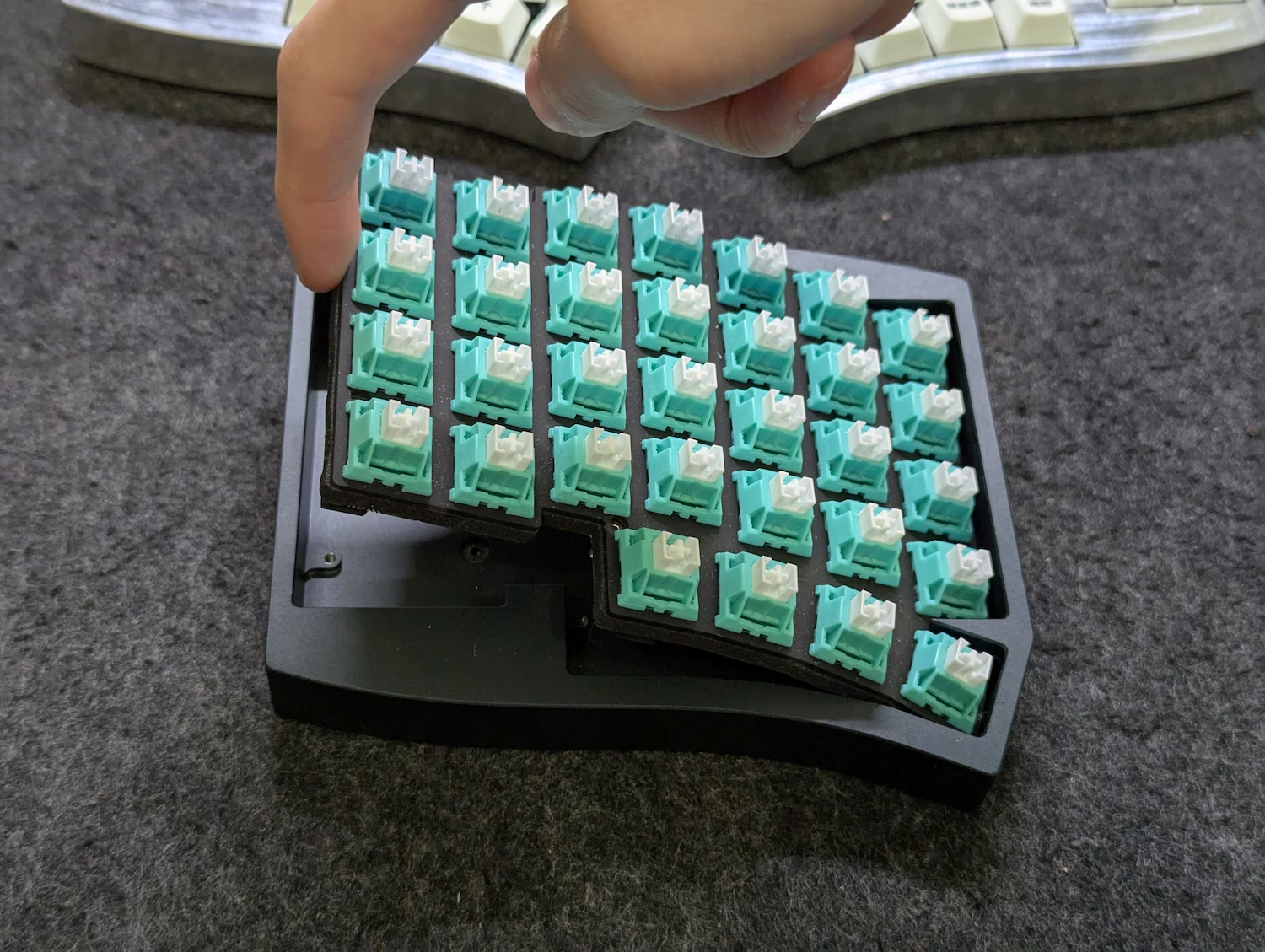
Pick up the internals and flip it over horizontally as shown below.
Keep an eye on the ribbon cable during the process - the cable should sit flat without any twists as the internals lower into the case.
If the cable does not sit roughly flat due to being fully twisted or whatnot, un-latch the cable and retry the assembly process.
-
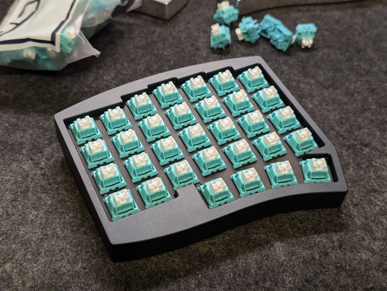
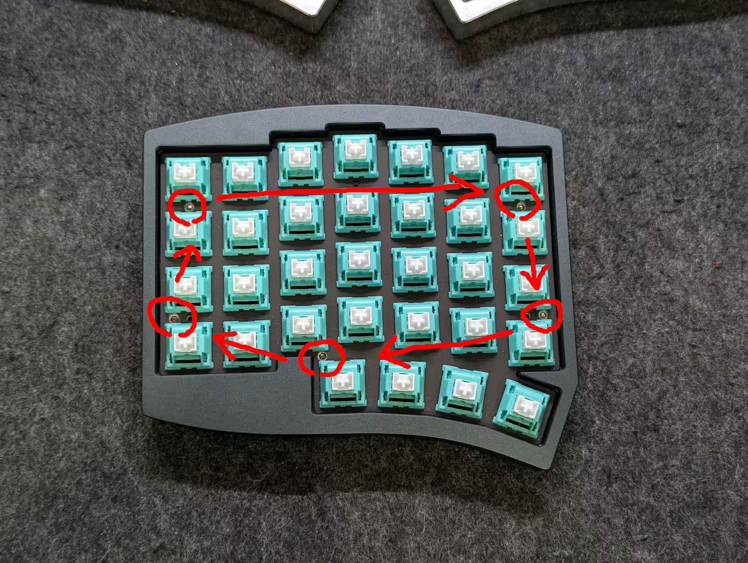
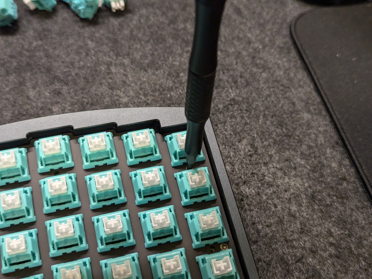
Screw the internals into place by turning the captive shoulder screws between the plate and PCB.
Before screwing them in, rotate the screw counter-clockwise until you hear a “click” - this is the sound of the threads engaging.Do not screw a single one in all the way at once, as this will pull the PCB and plate apart.
Instead, rotate each screw around 180 to 360 degrees at a time in clockwise order.
-
Once all the screws are in as far as they will go, connect the now-assembled half to the PC for testing.
Yes, the Altair will function even with just one half.Connect the outer USB port (the one near Esc/Backspace, not the one near spacebar) to the computer, and verify that it shows up as a keyboard.
All keys should function (aside from the layer key next to the spacebar which will seemingly do nothing - you will learn how to use this later in the learning guide).
Assembling the other half
The right half assembles in an identical way - simply repeat the build guide with the left/right mirrored, and you should have both halves assembled.
Once you test that the right half is also functioning as a keyboard, proceed to the next page for hooking them together.
Next Page