Altair(-X) Build Guide
Pages
Altair(-X) Build Guide - Page 4
Assembling the internals
-
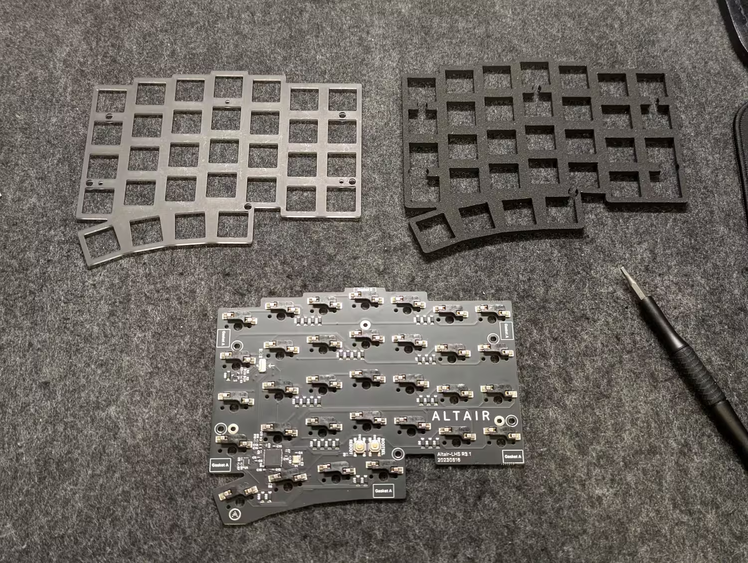
Prepare the following parts:
- One of the plates (they are reversible, so the left/right half plates are identical),
- The PCB for the left hand side,
- A foam midlayer if you purchased one and plan to use it,
- The screws and gaskets,
- The switches you’ll be using for the build.
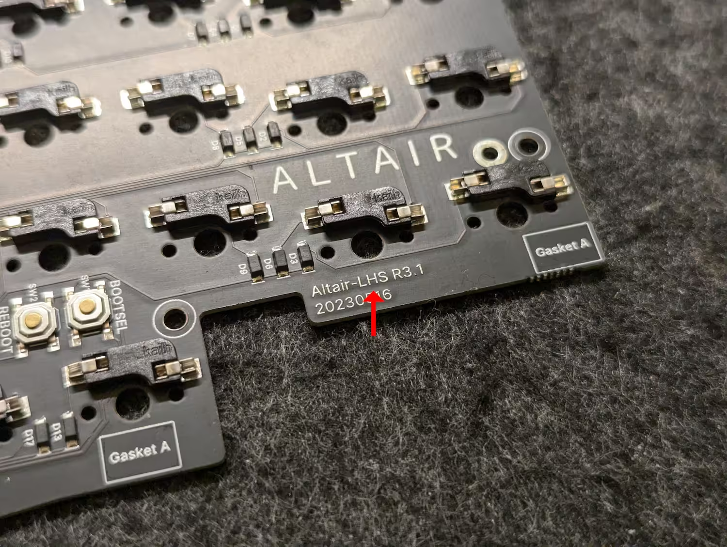
The PCB can be identified by the “LHS” (left-hand side) marker located here.
-
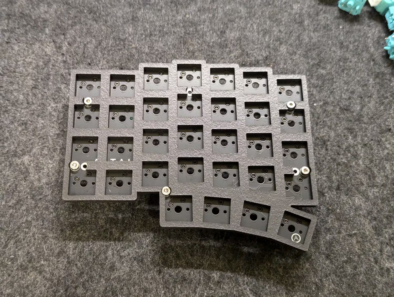
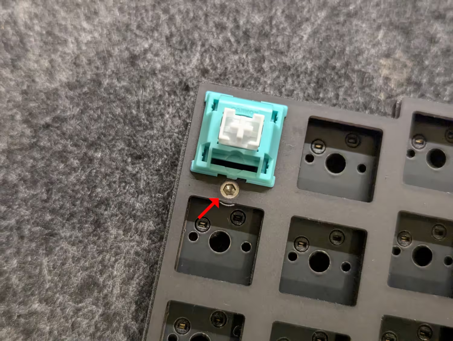
Place down three switches, then place the PCB atop to float it in the air.
-
Fit 5 of the provided “Shoulder Screws” (the screws with a small column between its head and threaded bit) into the 5 circled holes.
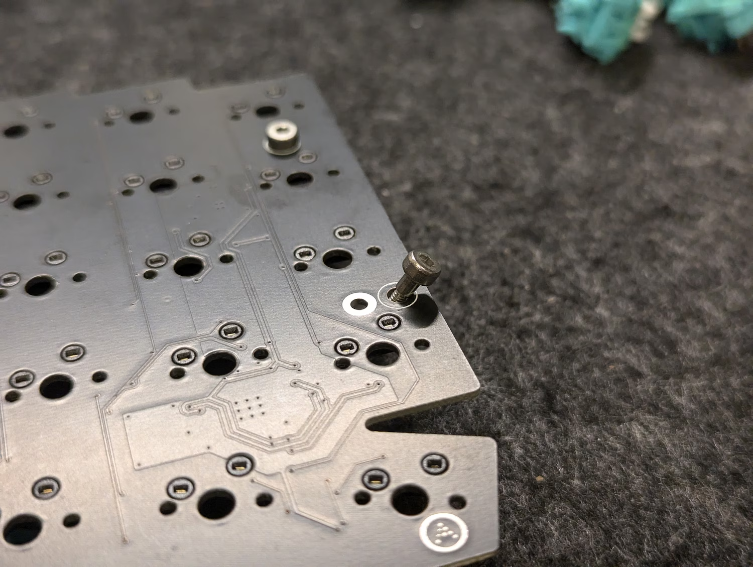
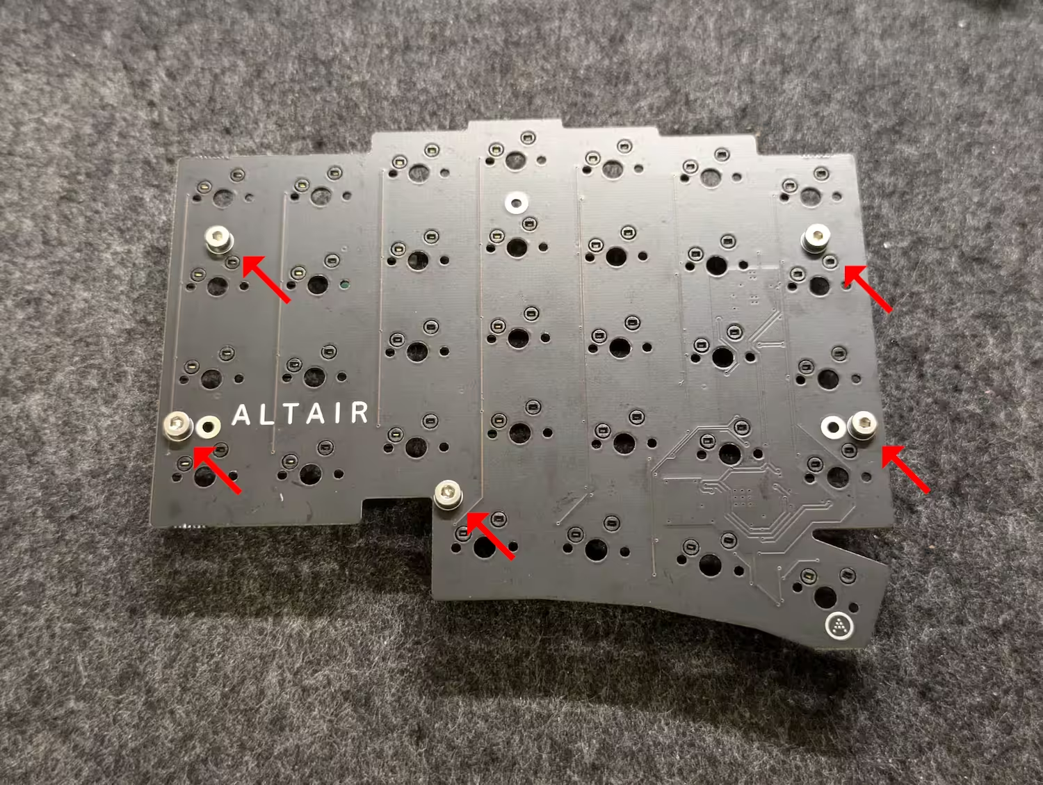
-
If you are using the foam midlayer, stack it atop the PCB and align it into place.
-
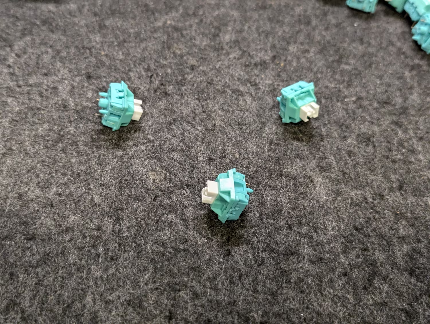
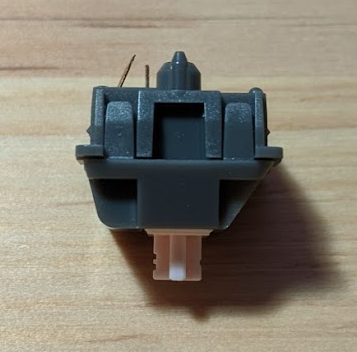
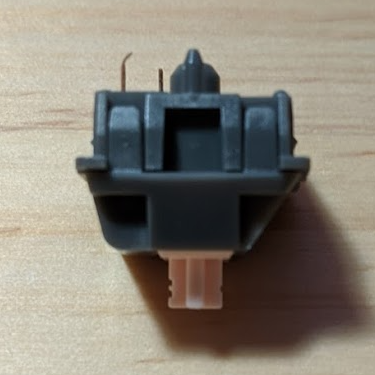
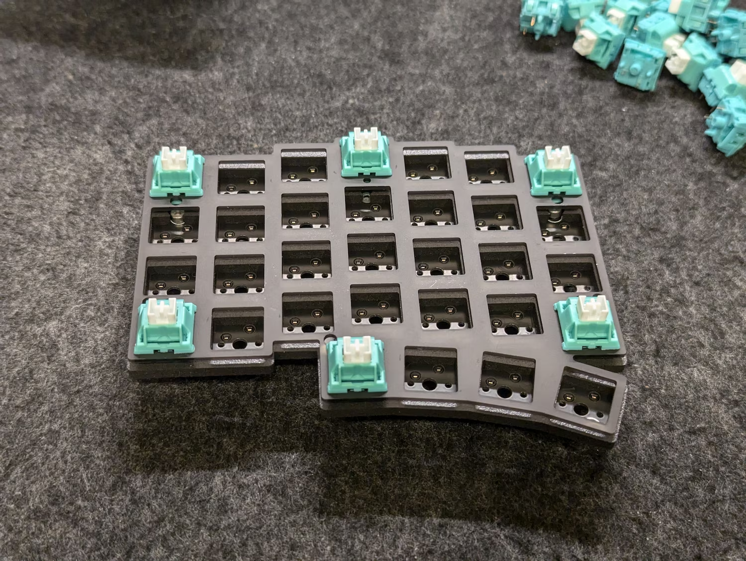
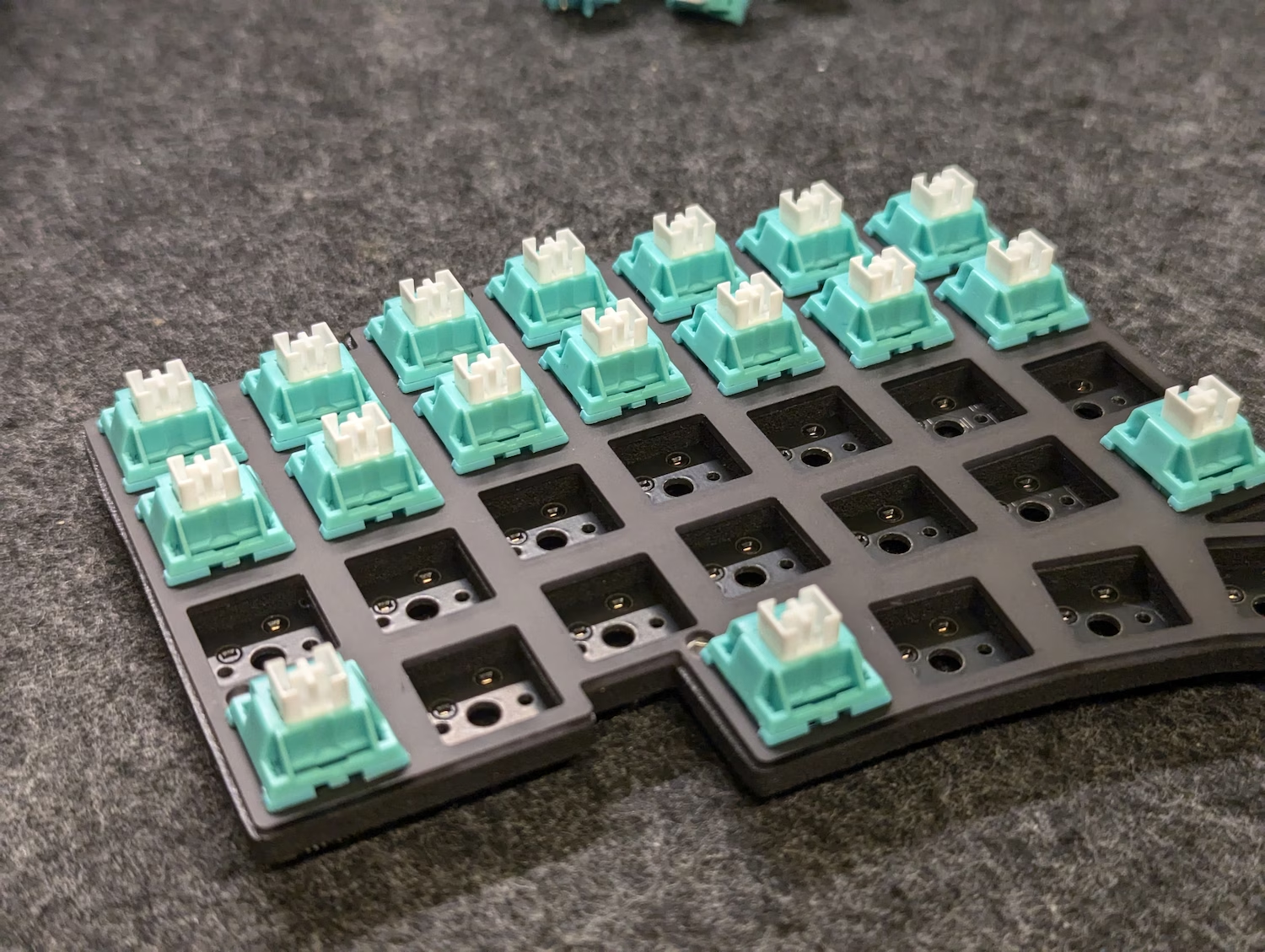
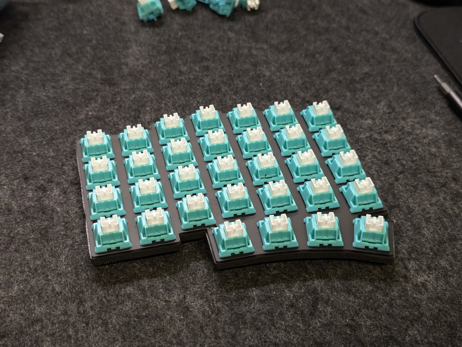
Separately, prepare the plate by installing 6 switches around the corners.
The photo below shows the recommended switch locations.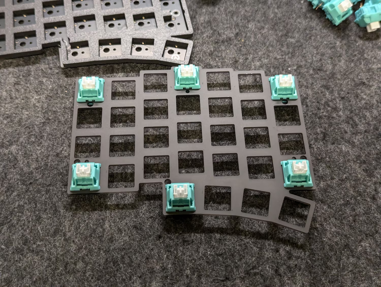
Verify that all 6 switches have straight pins - if you spot any bends like the ones below, bend them back into shape.
-
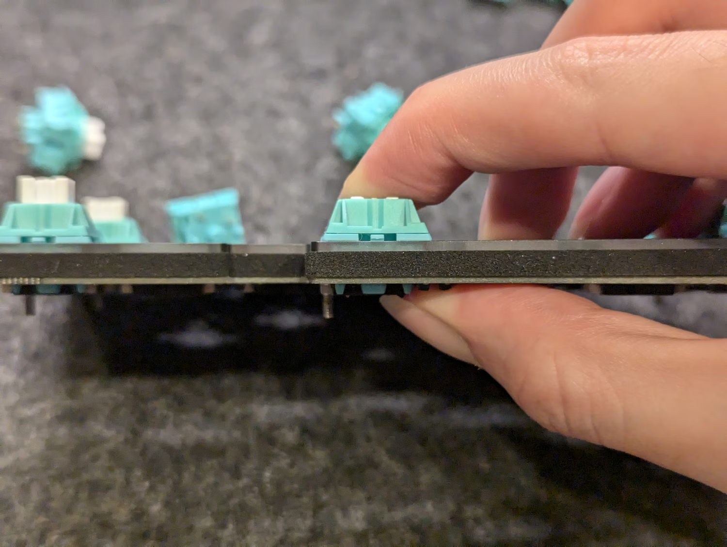
Place this plate-switch assembly onto the PCB-screws assembly, then push them together.
Once assembled, check the following:
-
The plate and PCB should be pushed all the way together, with the switches both clipped into the plate and making firm contact against the PCB.
-
The two pins of each switch have successfully made it through each socket, rather than being bent out of shape and crumping against them.
-
All five shoulder screws are now captive between the plate and PCB.
-
-
Install the remaining switches.
For each switch, verify that the switch pins are not bent, and insert them all the way until they clip into the plate and make firm contact against the PCB.
-
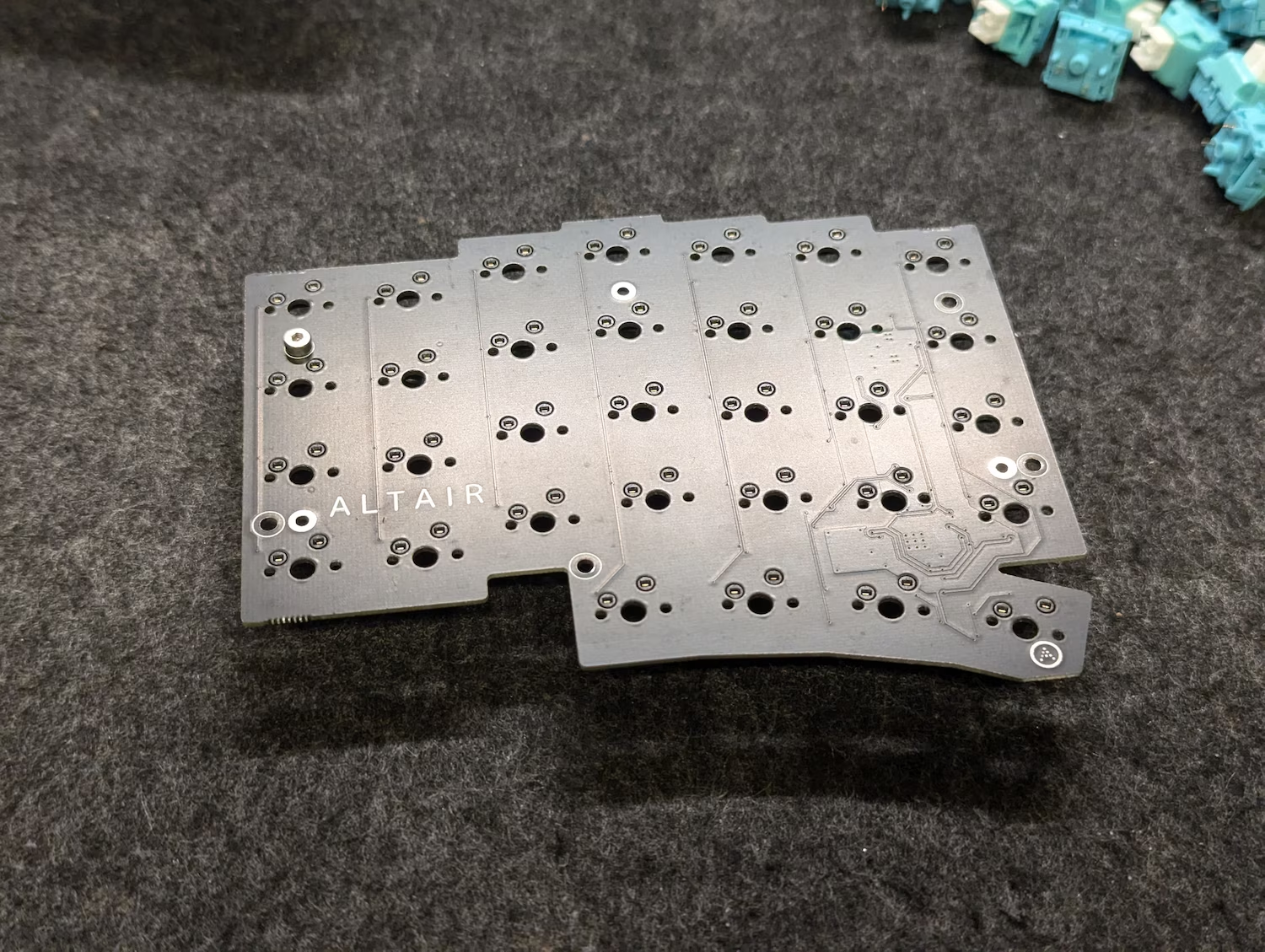
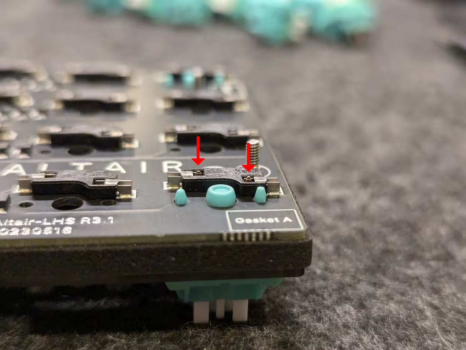
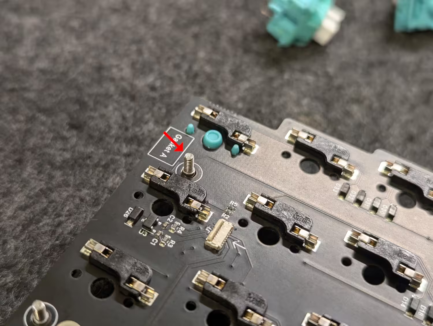
Flip the assembly upside-down.
Install the large gaskets into the locations shown below (marked with rectangles labelled “Gasket A” on the PCB).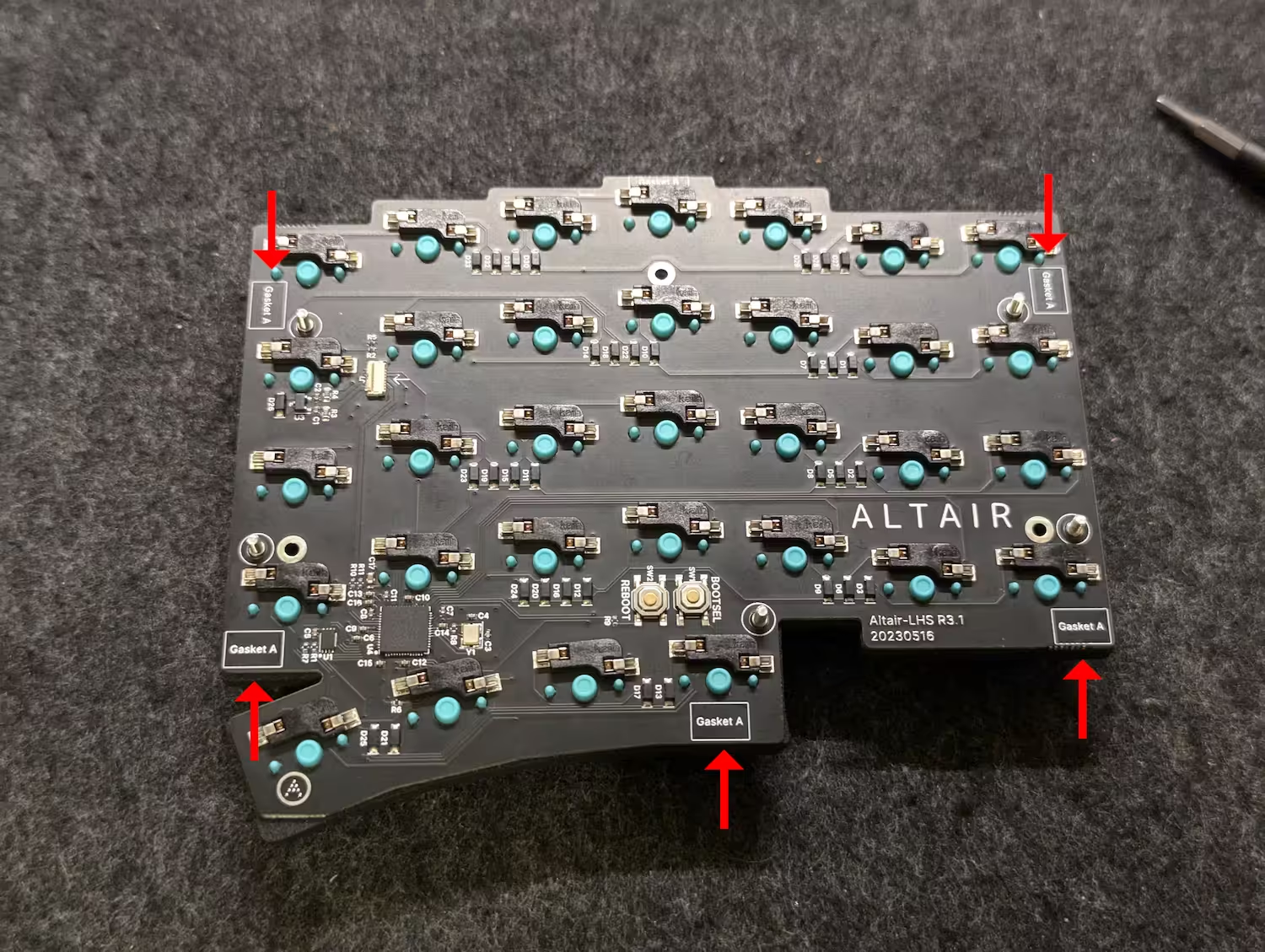
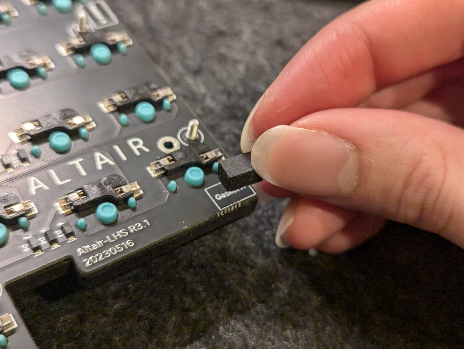
-
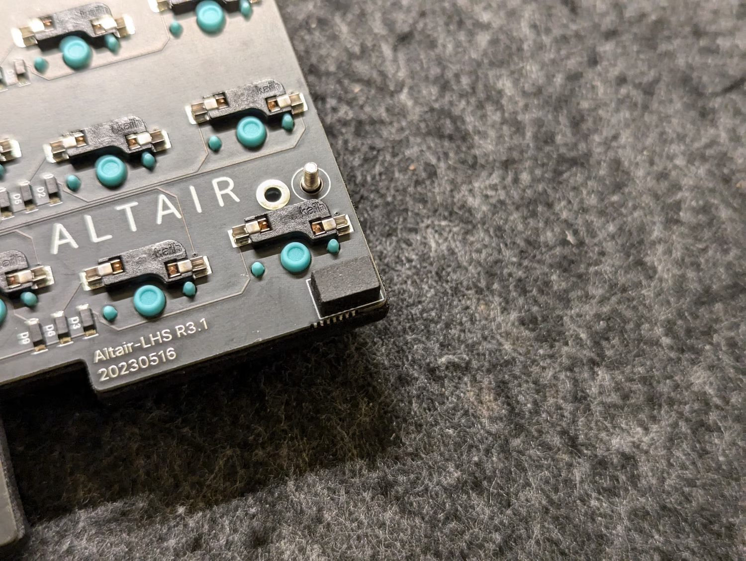
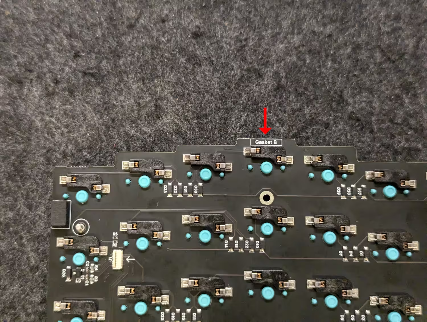
Install the small/thin gasket into the location shown below (marked with a rectangle labelled “Gasket B” on the PCB).
The internals assembly is now complete.
It is now time to put it all together.