Altair(-X) Build Guide
Pages
⭢ Preparing the USB board/daughterboard
Assembling the internalsPutting it all togetherKeymap assembly and combined testingAltair(-X) Build Guide - Page 3
Assembling the left half
For the sake of simplicity, we will assemble one half at a time.
Place the left case half on a working surface clean of debris.
Weight tuning
First, verify that the weight is properly secured to the case.
- Using the provided hex key, loosen one of the three weight screws, then tighten just enough to be secure.
Too loose may cause the screw to loosen over extended use, while overly tightened may cause undesirable resonances. - Repeat on all 3 screws.
Preparing the USB board/daughterboard
-
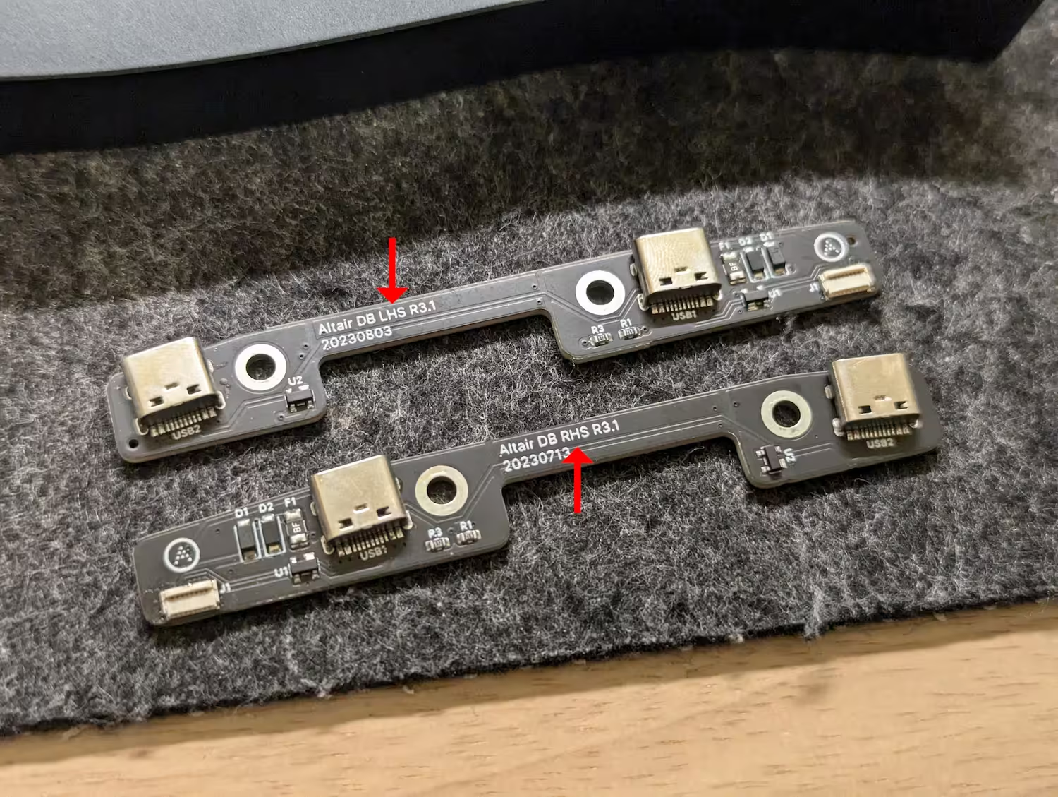
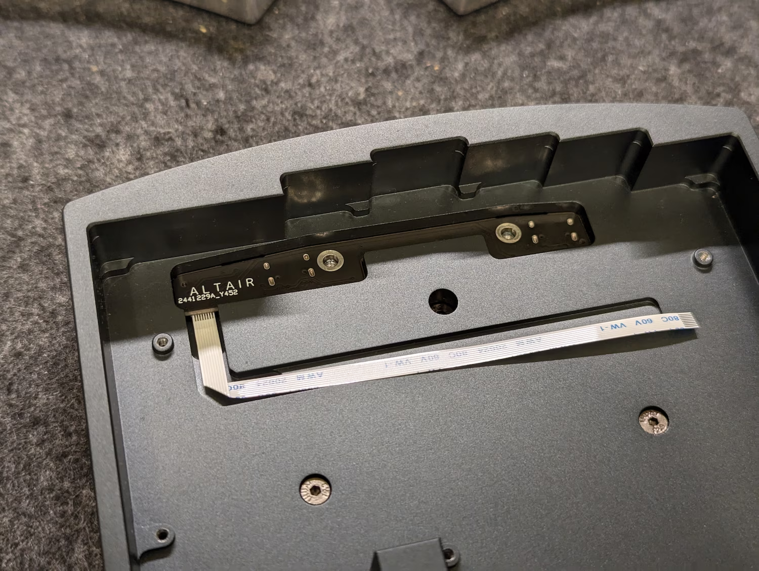
Locate the USB daughterboard for the left half.
a. If you unit arrived with daughterboards packaged individually, find the correct half.
The daughterboards are labelled for identification - “LHS” denotes “left-hand side” while “RHS” denotes “right-hand side”.
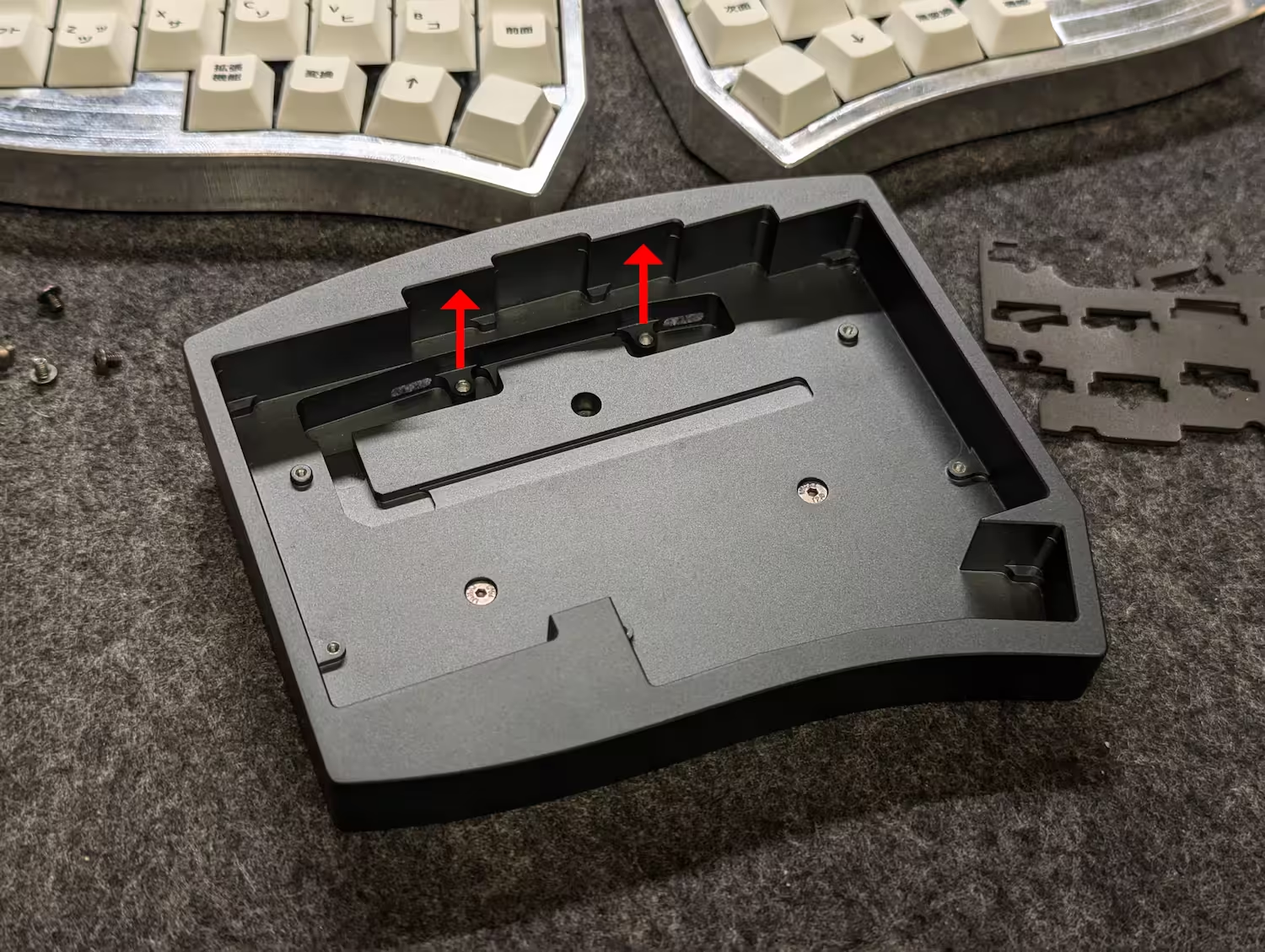
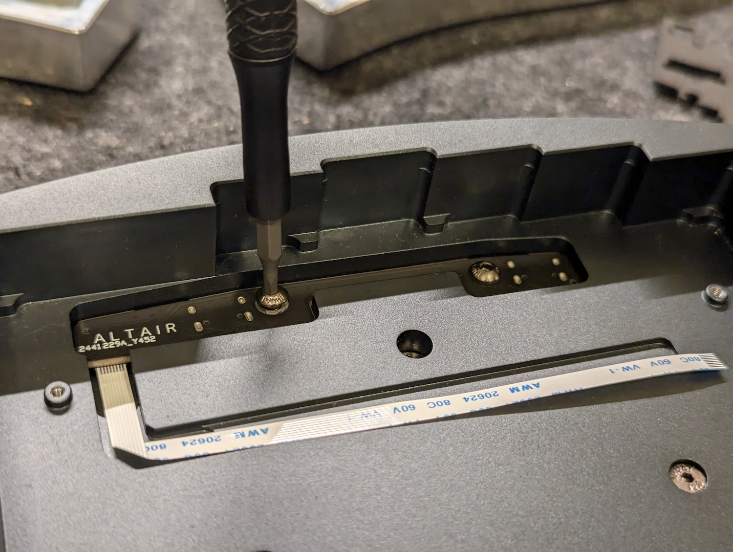
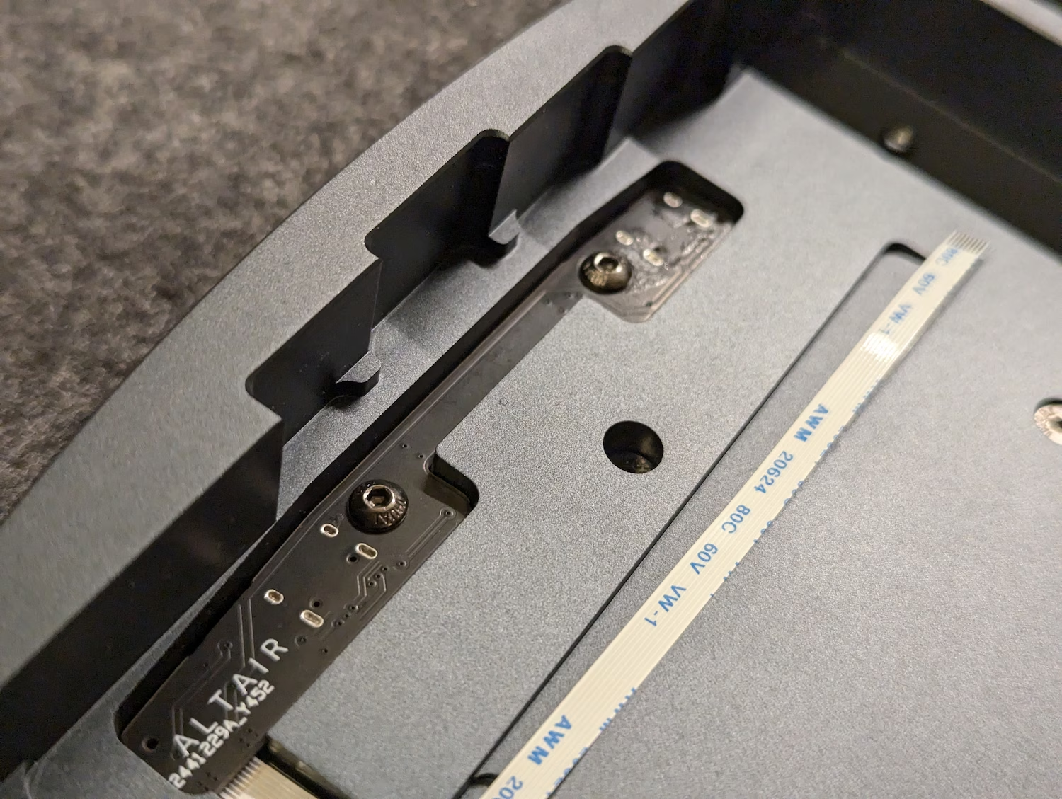
b. If your unit arrived with the daughterboards pre-installed into the case, use the provided hex key to remove the two screws holding it in place, then remove the daughterboard from the case.
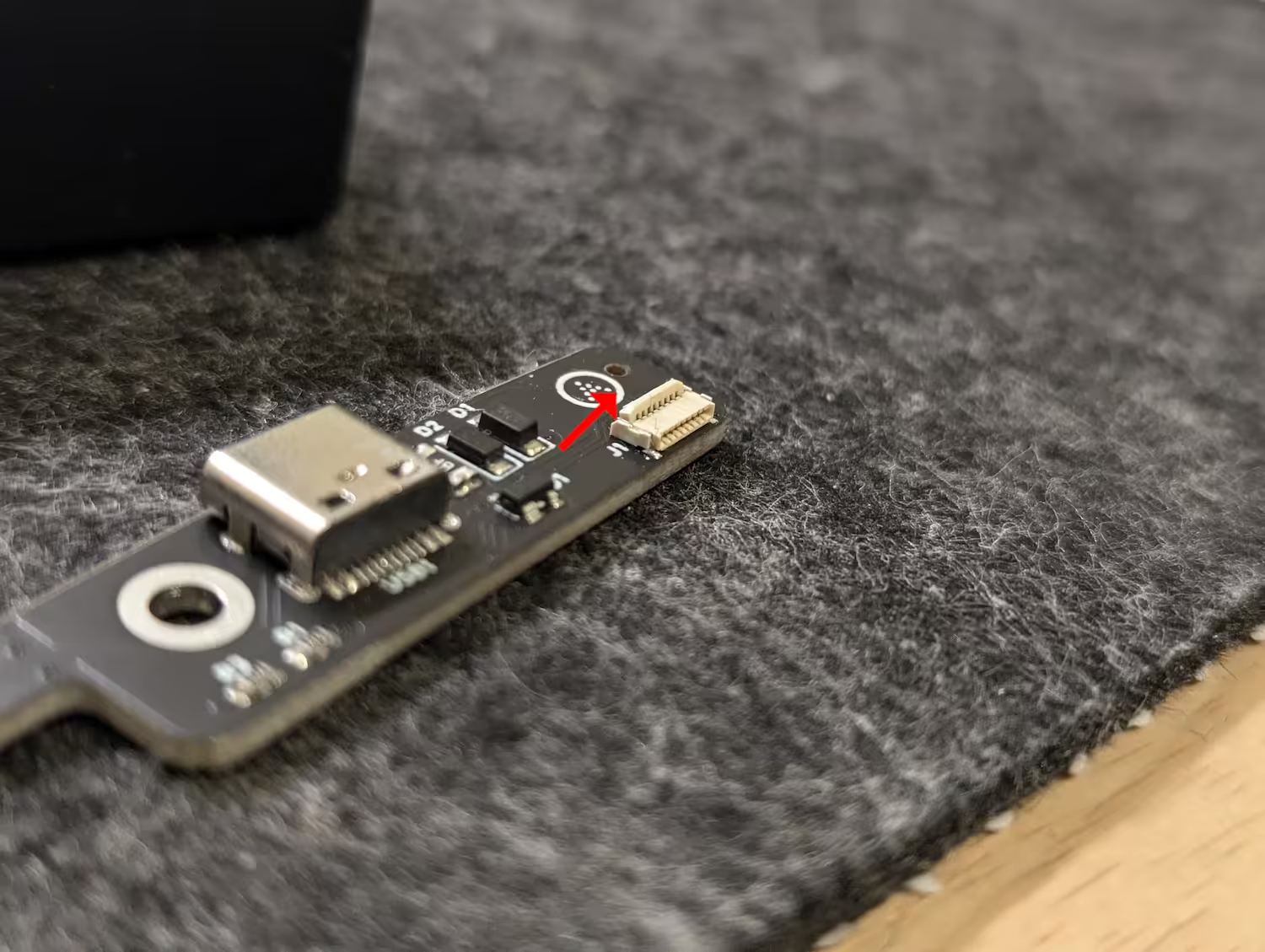
-
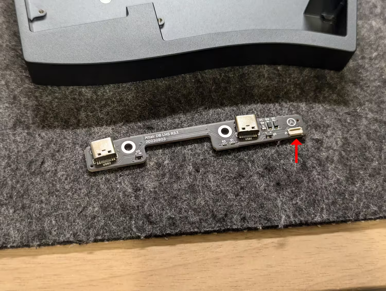
Locate the connector for the FFC (flat flexible cable) - this is the tan rectangular component located here.
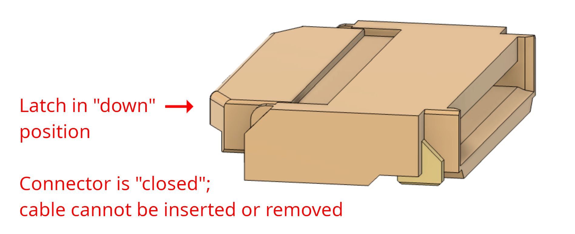
A note on FFC connectors
The Altair uses FFCs (flat flexible cables) due to space constraints and the need to transmit many signals between the mainboard and daughterboard.
These FFCs are thin strips of copper foil clad in plastic on both sides to create a ribbon-thin cable that can bend and flex.
These FFC cables require special connectors - Altair(-X) specifically uses “back-flip” connectors for the sake of reliability and ease of assembly.
-
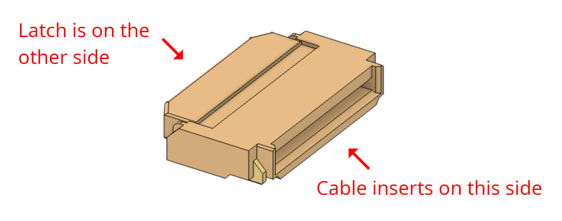
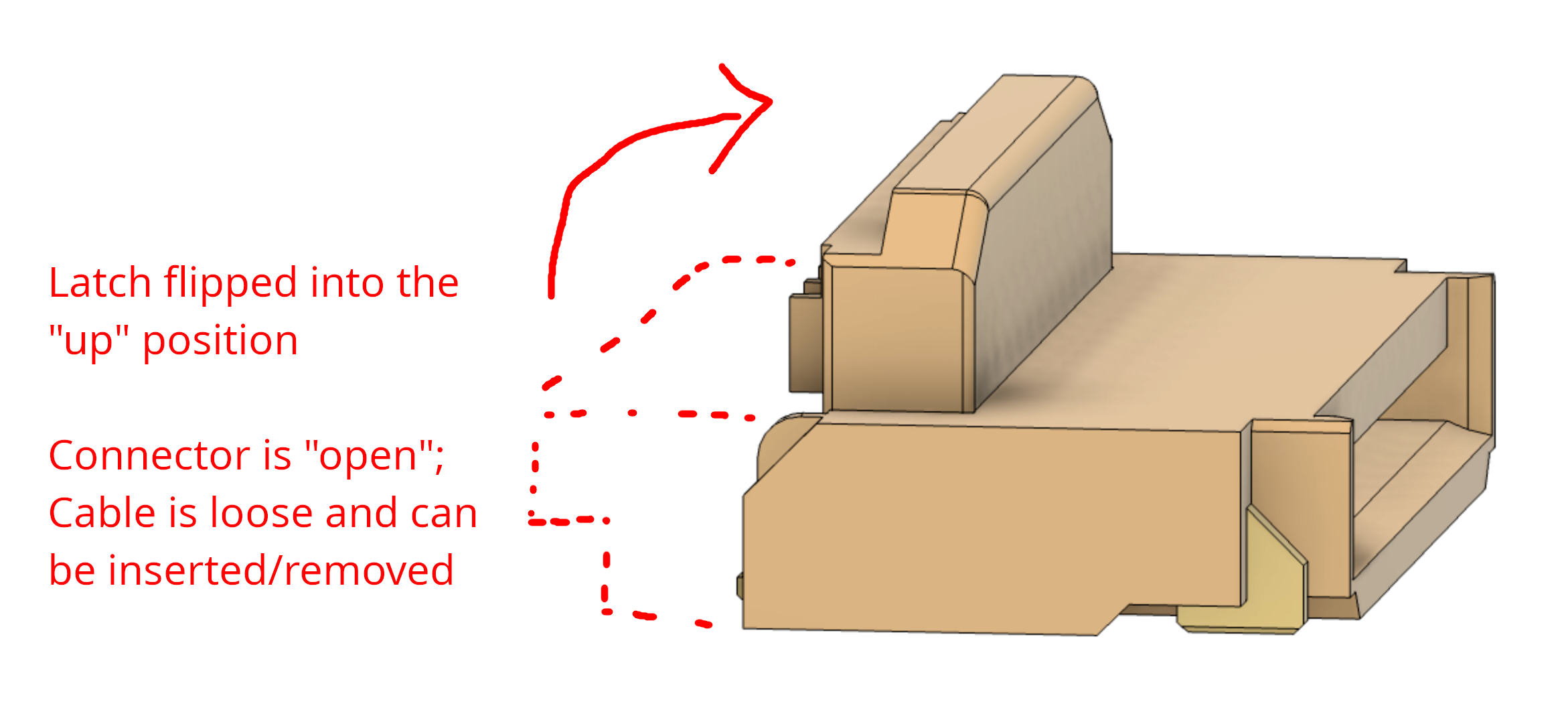
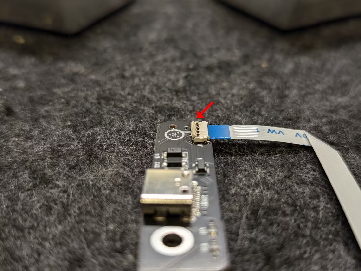
With this knowledge on the FFC connector, prepare the connector for assembly..
If the latch at the backside of the connector is sitting in the “down” position parallel to the PCB, use your nails (or spudger/flat-head screwdriver/etc) to carefully lift the latch at the back into its “upright” position.
-
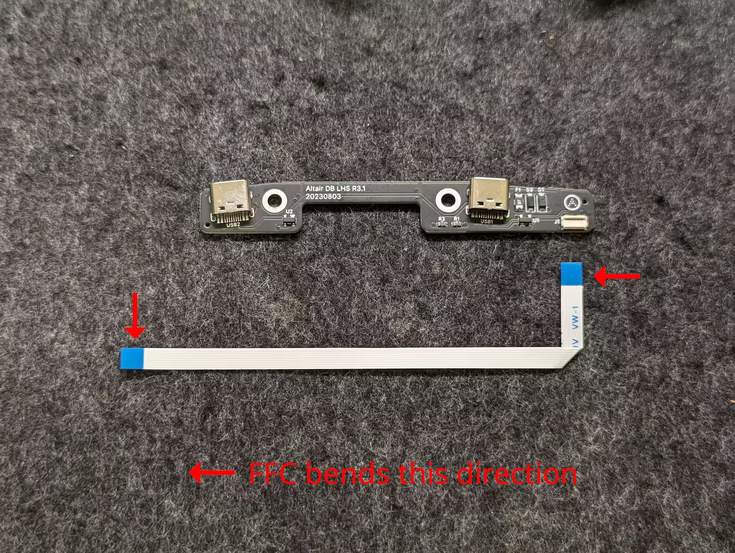
Locate the FFC (flat flexible cable/ribbon cable) for the left half.
The package should have arrived with two of different bend directions - identify the one for the left half.- Place the daughterboard with the USB ports facing up.
- Flip the FFC so that the side with the blue tape on the ends is visible (rather than the side with the silver metallic contacts).
- Place the short side of the bend so that it faces into the FFC connector.
- The long side should now bend towards the other end of the daugherboard.
-
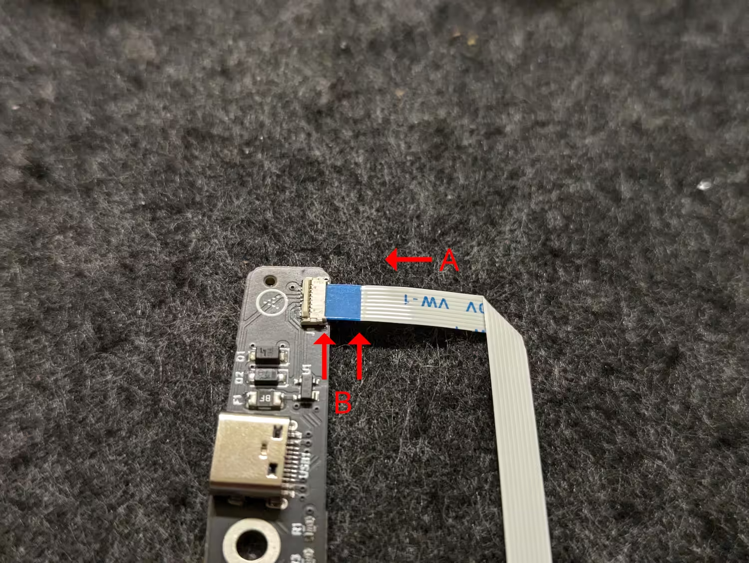
Insert the short arm of the FFC into the FFC connector of the daughterboard (A).
Once inserted as far as it will go, make sure that the cable isn’t severely bent to one direction or another - the short arm of the cable should be roughly perpendicular to the daughterboard’s edge, and the edges of the FFC connector and blue tape should be roughly parallel (B).
-
Secure the FFC into place by closing the latch on the FFC connector into its “down” position.
You may want to hold the cable in place during the process so it doesn’t bend.
Once completed, the latch should be roughly parallel to the PCB, and the FFC should no longer slide out when given a (very gentle) tug.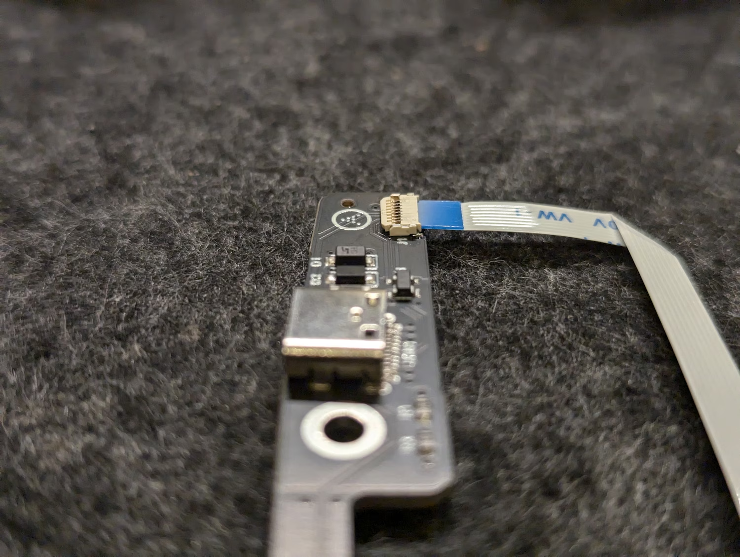
-
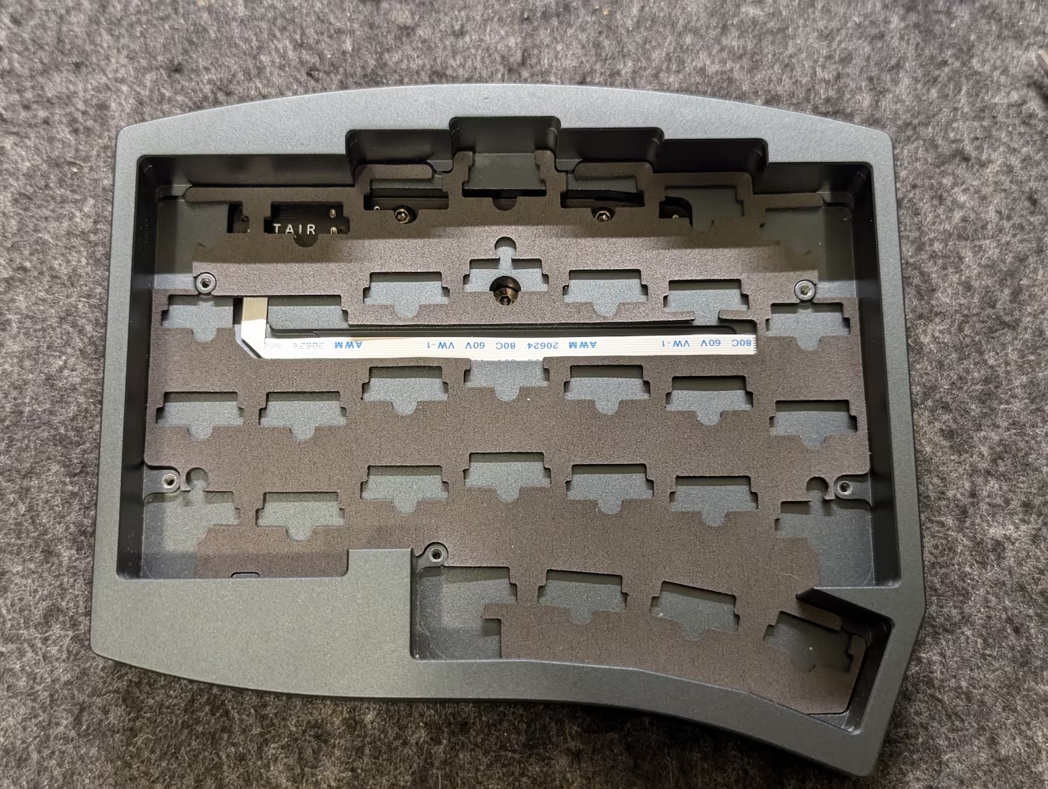
Install this assembled daughterboard-cable assembly into the case.
Lower it into the case with the USB port side facing down - the shape of the daughterboard and cable should end up matching the shape of the cutout on the case.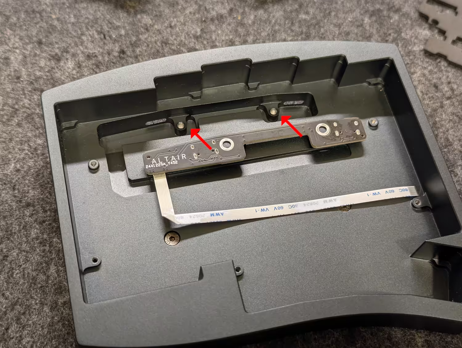
Screw the daughterboard into place using two of the round-head screws.
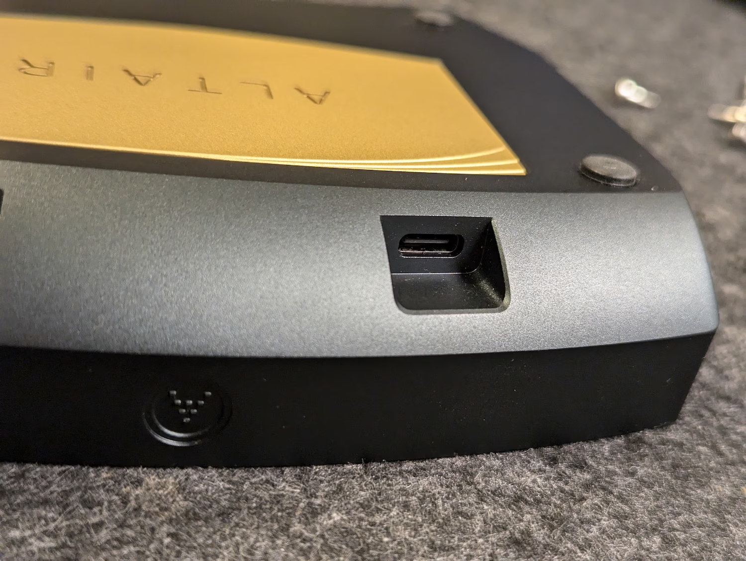
As confirmation, the USB ports should line up with their cutouts when viewed from the exterior of the case.
-
At this point, if you ordered the foam kits and plan to use any of the layers below the PCB, fit them into the case.
The daughterboard installation is complete.
It is now time to assemble the internals.